ARCHANGEL II
MARS LINE
Building the aircraft at Cyber-Toulouse.

Starting Archangel II
Archangel II - a hybrid spaceplane using a mix of traditional and new technologies to enable it to perform its mission of travelling the route between Earth and Mars.
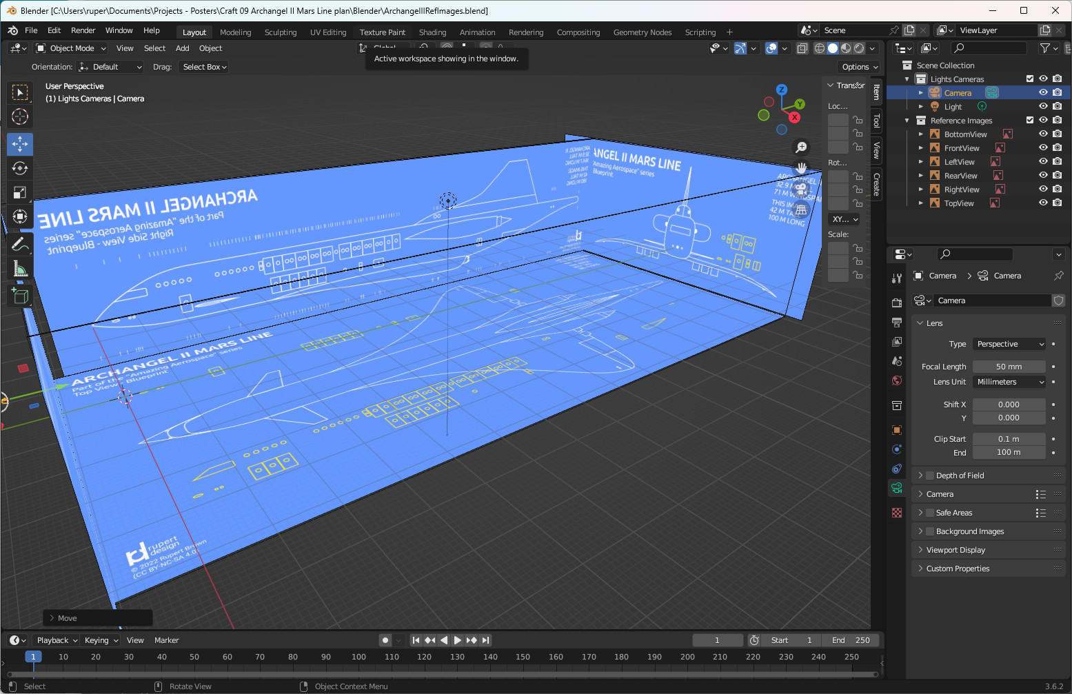
Archangel II - another build for Cyber-Toulouse, in the heart of the French space precinct. The first step is to lay out the blueprints as reference images.
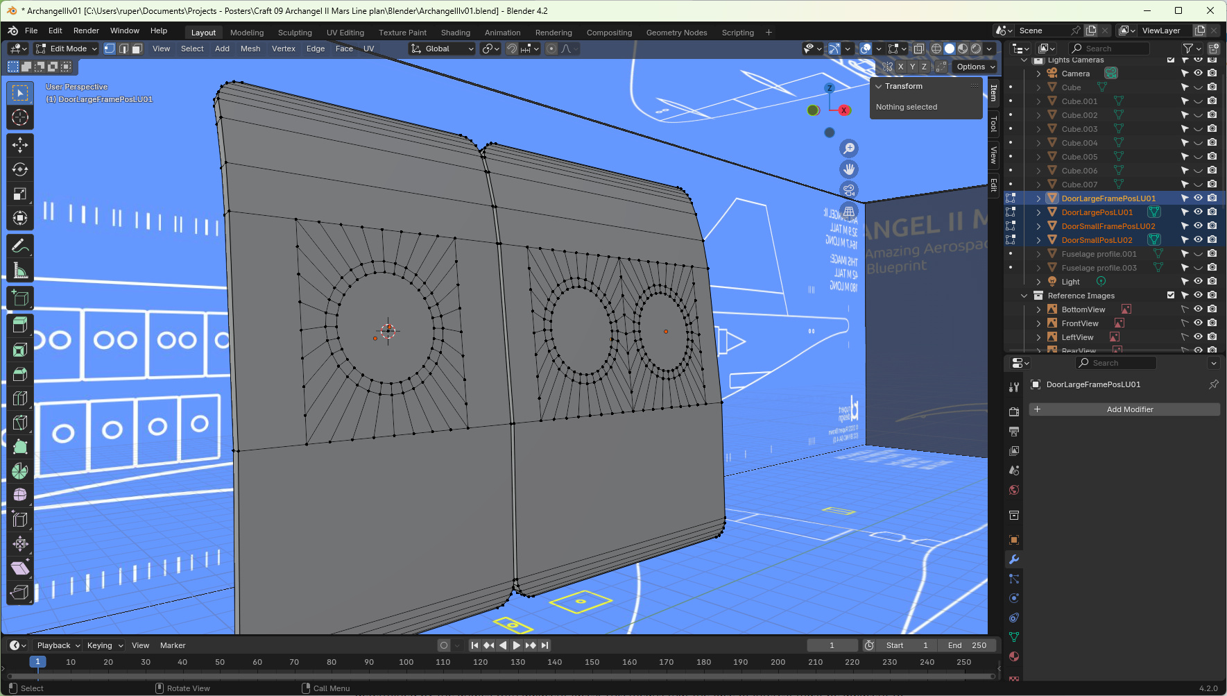
In Archangel II the passenger sleeping cabins double as "life boats". In an emergency, a cabin can be jetisoned into space to get people away from whatever disaster is unfolding on the ship. Each of the cabins has the life support equipment needed to keep people alive till they are rescued.
That means that the outer wall of cabins form an integral part of the hull of the ship. I could have used a simple texture to show that they are there, but decided to actually build them into the geometry. This is a lot more complicated, but makes it easier to create a scene with the cabins leaving the ship - if I want to at some later date.
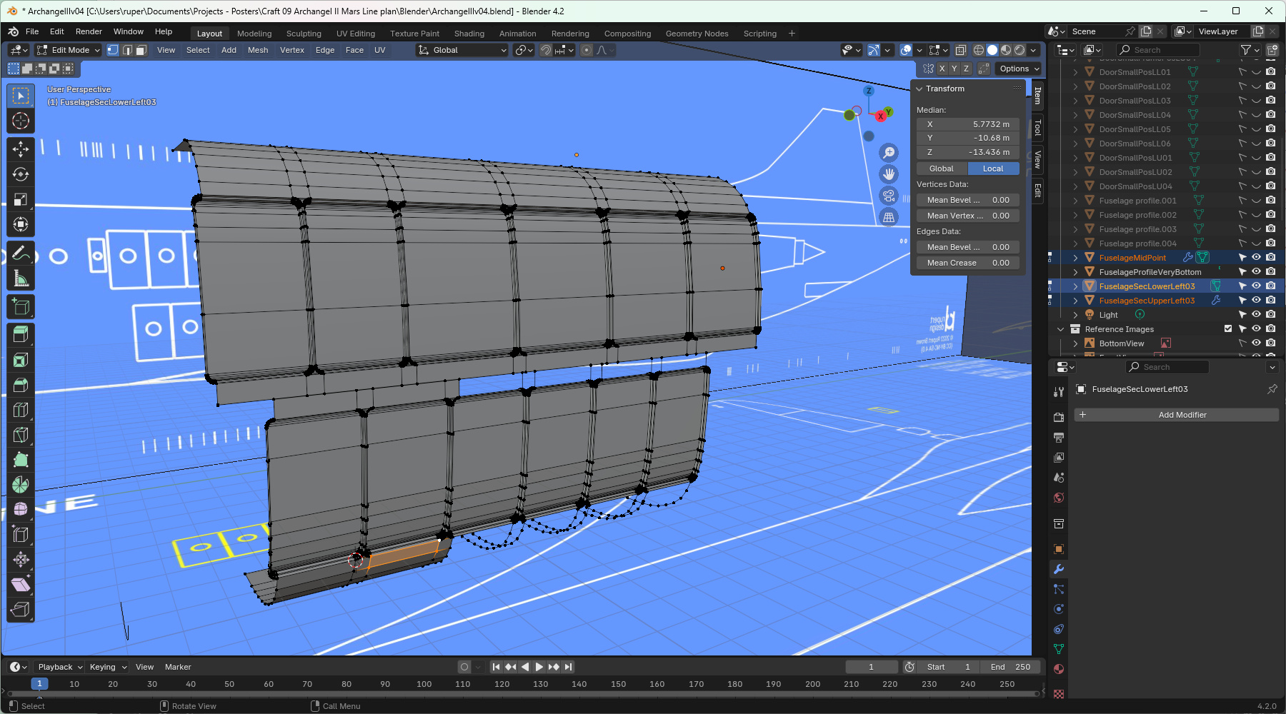
Archangel II Fuselage
Archangel II's fuselage is taking shape.
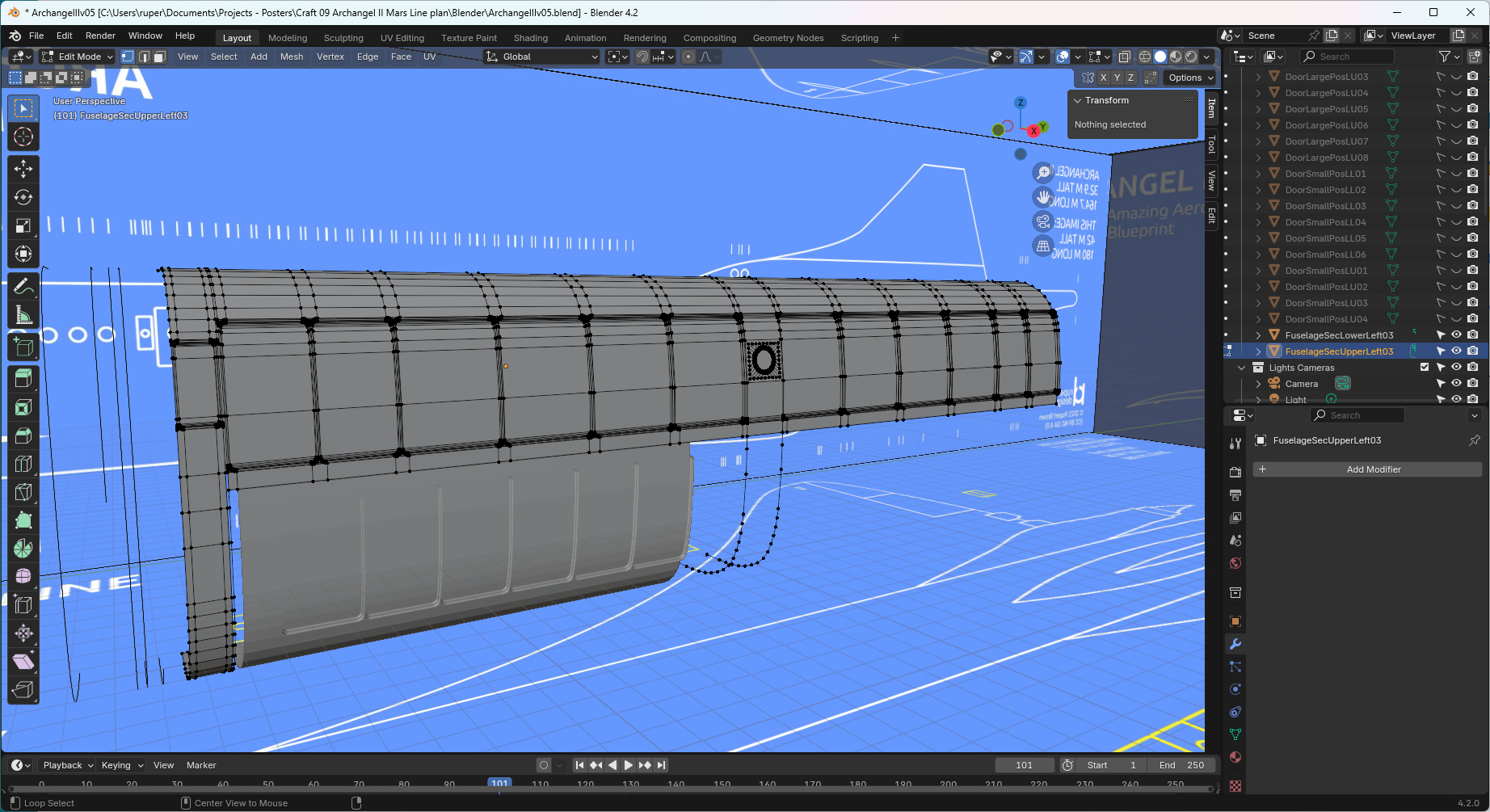
Crucially the fuselage is asymmetrical, so you can't build one side and then mirror it. Parts have to be built separately and then brought together. That is making for some interesting challenges.
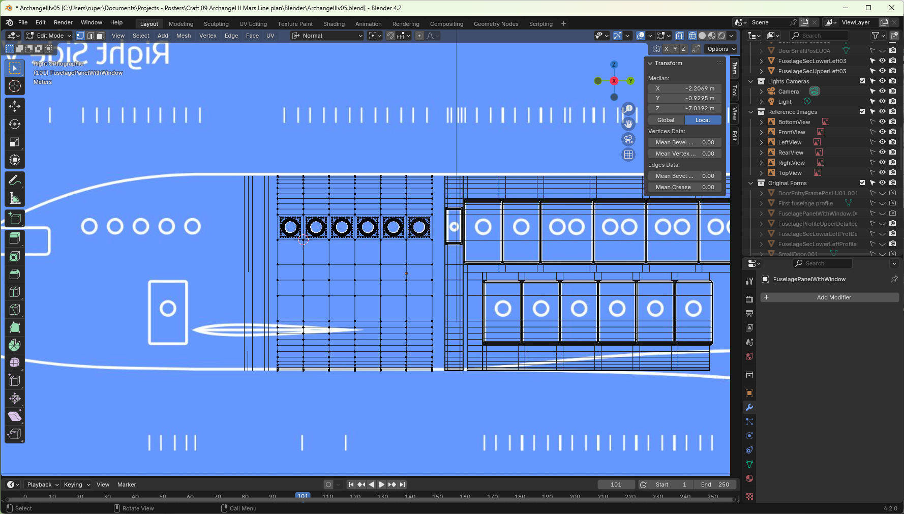
Archangel II Nose
There is quite a lot going on with the nose section of Archangel II. It narrows in the horizontal plane in a symmetrical way. In the vertical plane, the top of the fuselage is narrowing faster than the bottom. In this case I did scale geometry but made a lot of use of the 3D cursor to control how that scaling worked. I scaled different parts of the geometry independently of each other to get the effect I wanted.
I was very conscious of trying to maintain geometry and XYZ positions of vertices when I built in the windows and the windscreen. Generally that seemed to work well, but I'm aware that the very top right of the furthest forward window isn't quite where I want it. But it is one of those trade-offs. To try and adjust it risks damaging the whole mesh. It would take time and be very fiddly. The current geometry is probably "good enough", so I ended up leaving it the way it is.
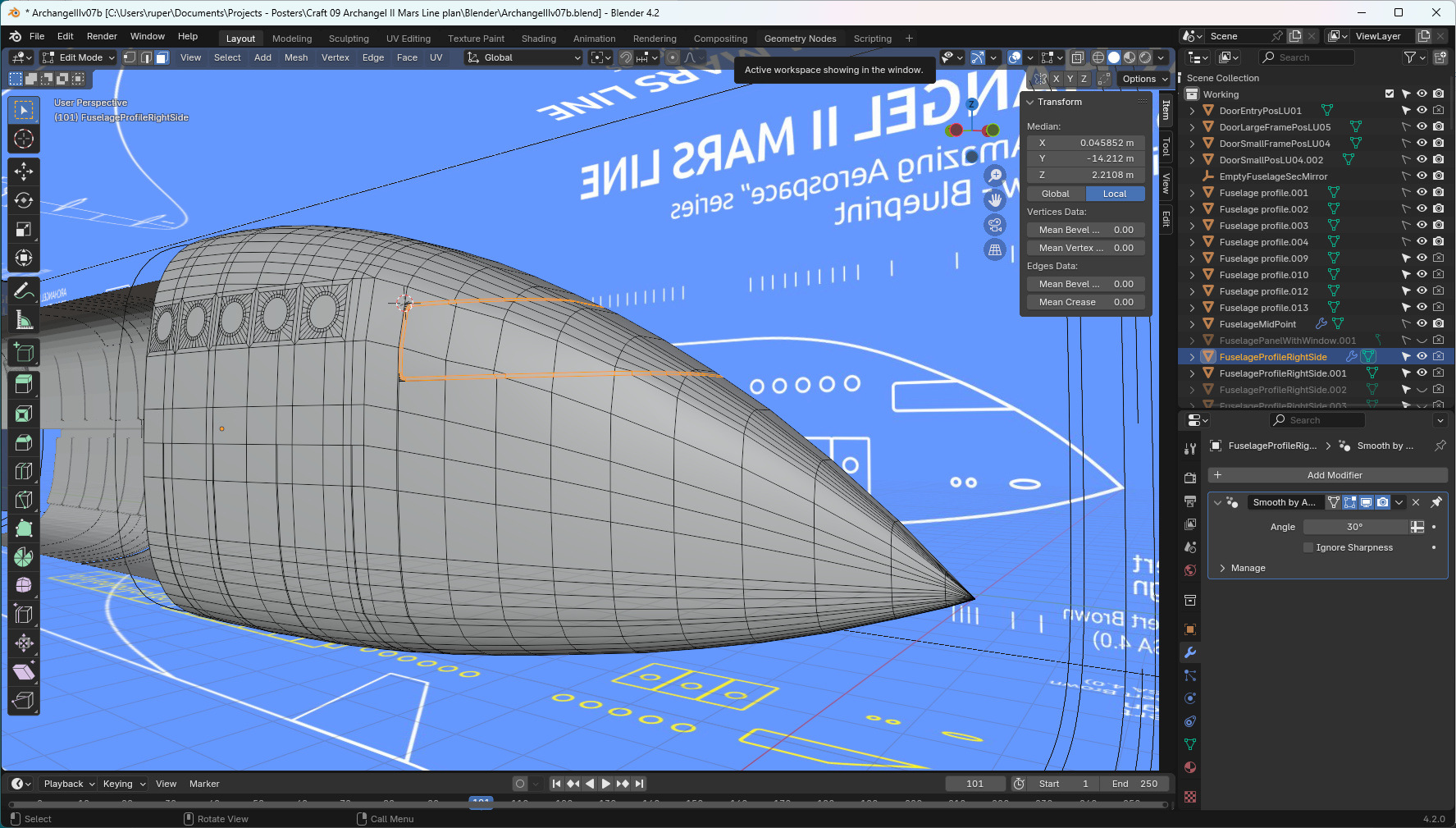
In space, wings and flying surfaces are of no use at all when it comes to manoeuvring. In space - given Archangel II's technology - the ship needs jet (reaction) based thrusters, typically at the front, rear and side, and on the ends of the wings, to give it full three dimensional control. This image shows how I sunk holes into the nose to create the thruster ports.
When in an atmosphere, it is not wise to simply leave the ports as holes because of the drag and turbulence impacts they would have on the ship. So for every thruster port I also created a port cover (not shown). That is a simple mesh duplicate and separate operation, with some finishing off.
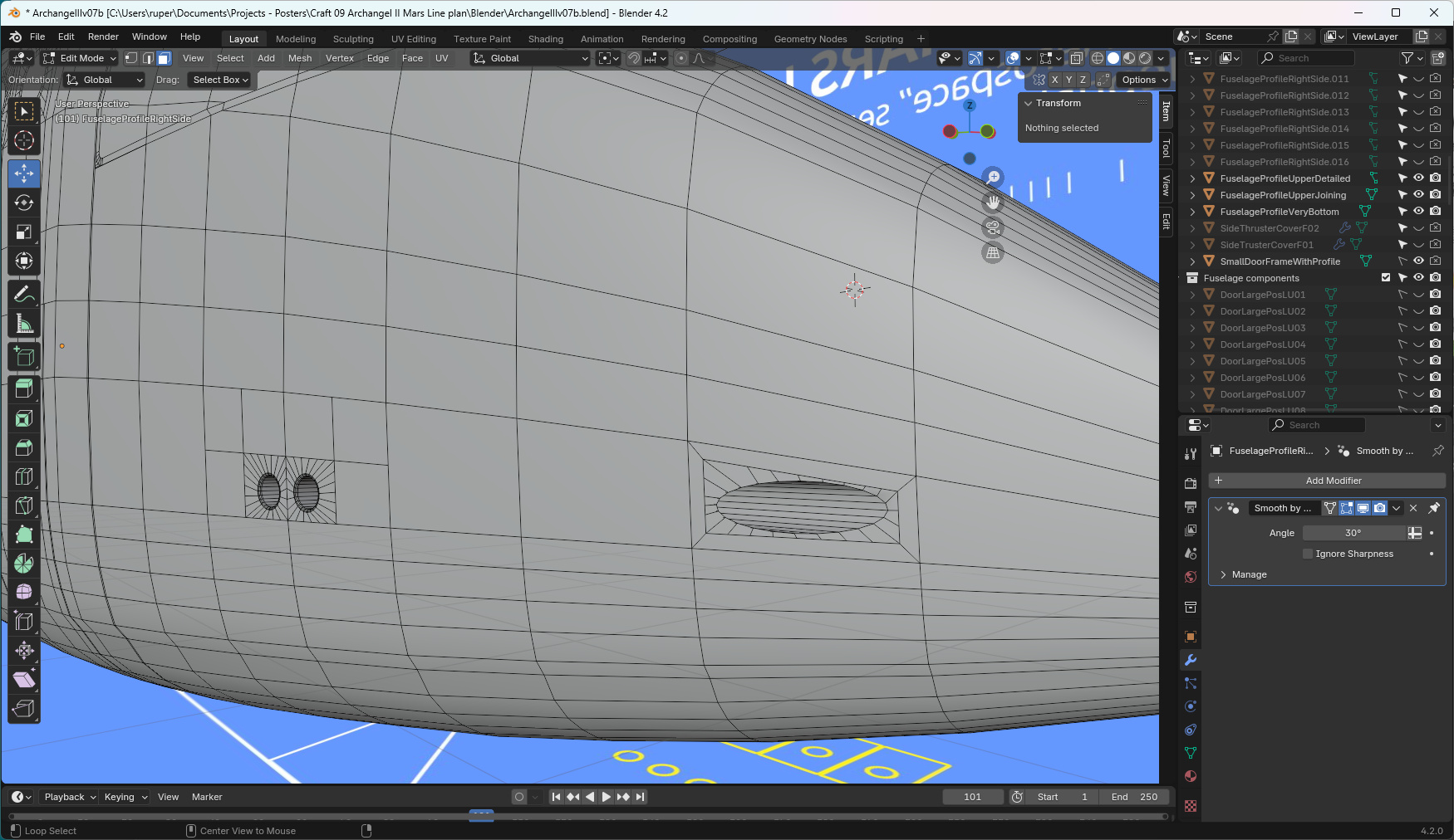
This image shows the nose geometry more or less complete. Visible are three crew pods on this side. The left side only has the one pod.
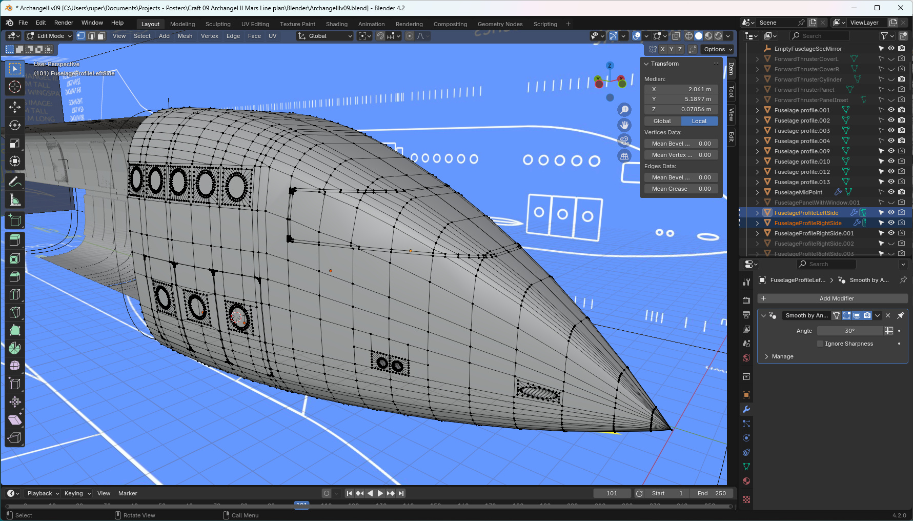
Archangel II Tail
Archangel II's tail is a big part of the fuselage. It houses a lot of the ship's equipment, including the all important tokamaks that produce the energy for the ion drive engines. It also houses the staff Dark Star bar which probably has the best views of space.
Its shape is dictated by the height of the fuselage, the need to allow for rotation at take-off, and that for Earth's atmosphere, it provides a good aerodynamic conclusion to the ship i.e. it can't be too stubby.
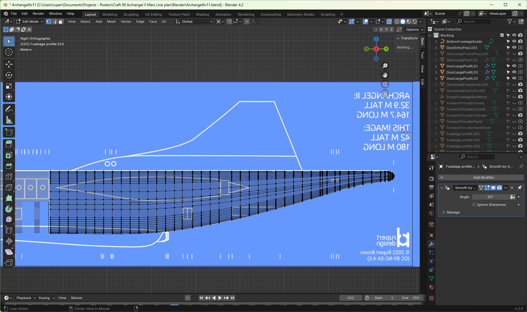
The image below shows the tail in the context of the rest of the fuselage. By this point all the different parts of the fuselage have been connected together. The asymmetry of the ship, and it's pods, door and windows, lead to some interesting mesh geometry.
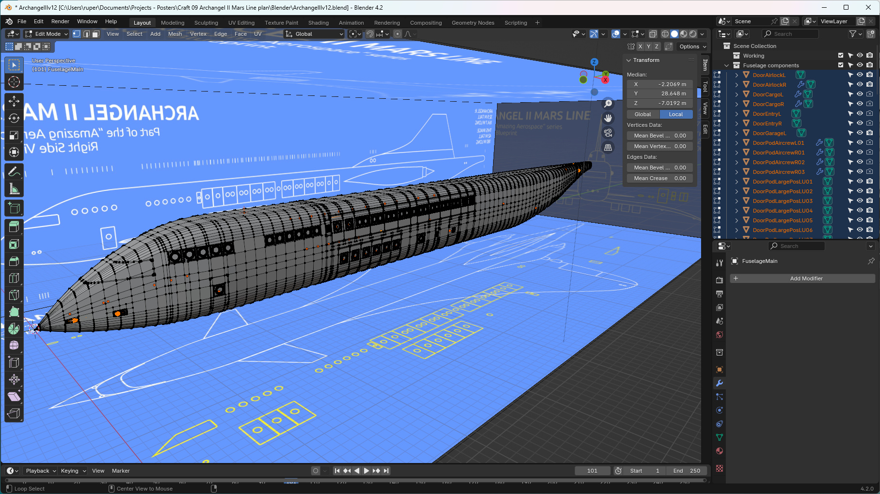
Thankfully it's beginning to look like the ship I imagined. This image is with smooth shading turned off.
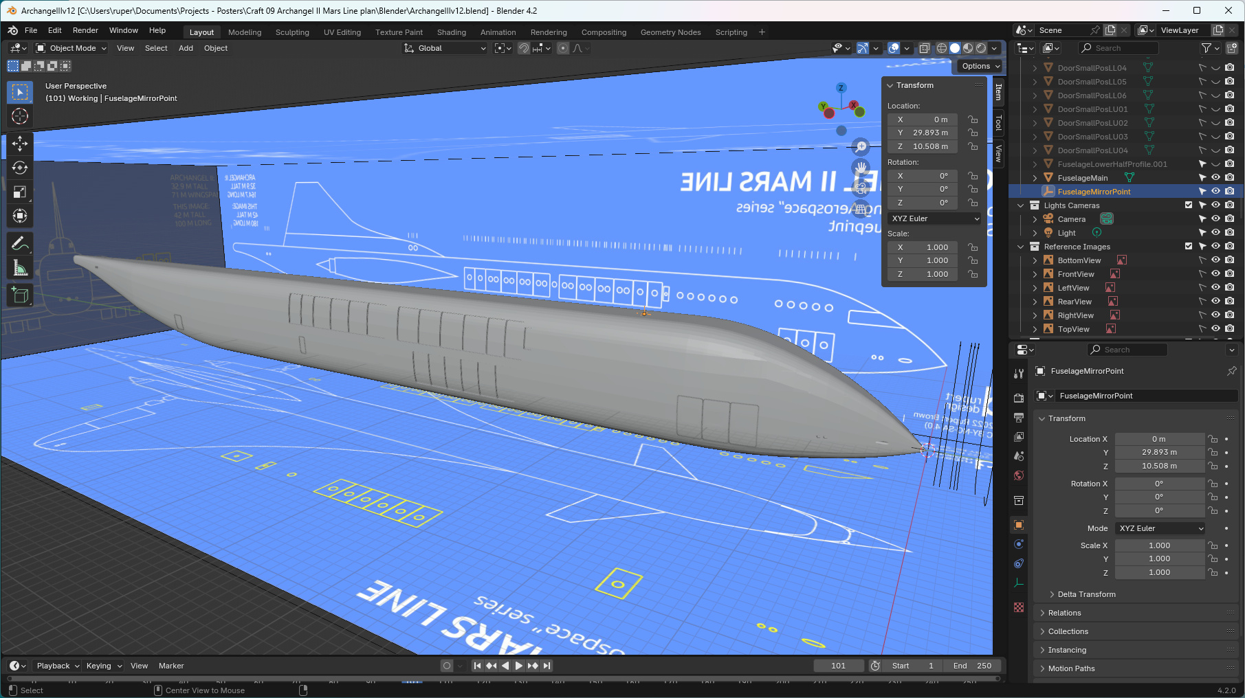
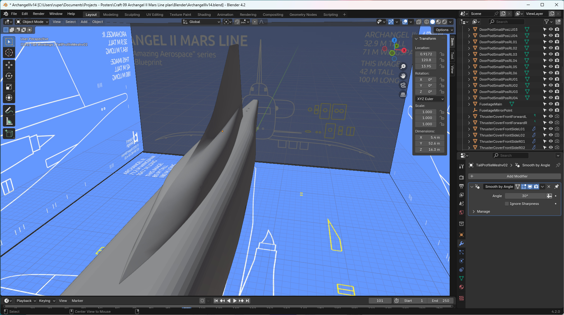
The vertical stabiliser houses another important amenity - that of the Star Deck Observatory and Galaxsia bar.
This is another good example of how I like to reduce geometry when things get smaller - rather than just scale the same amount of geometry down. In the image below you can see how I've used and removed geometry to build up the profile of the vertical stabiliser, and create that sharp leading edge. My experience so far is that it is a technique that produces good results.
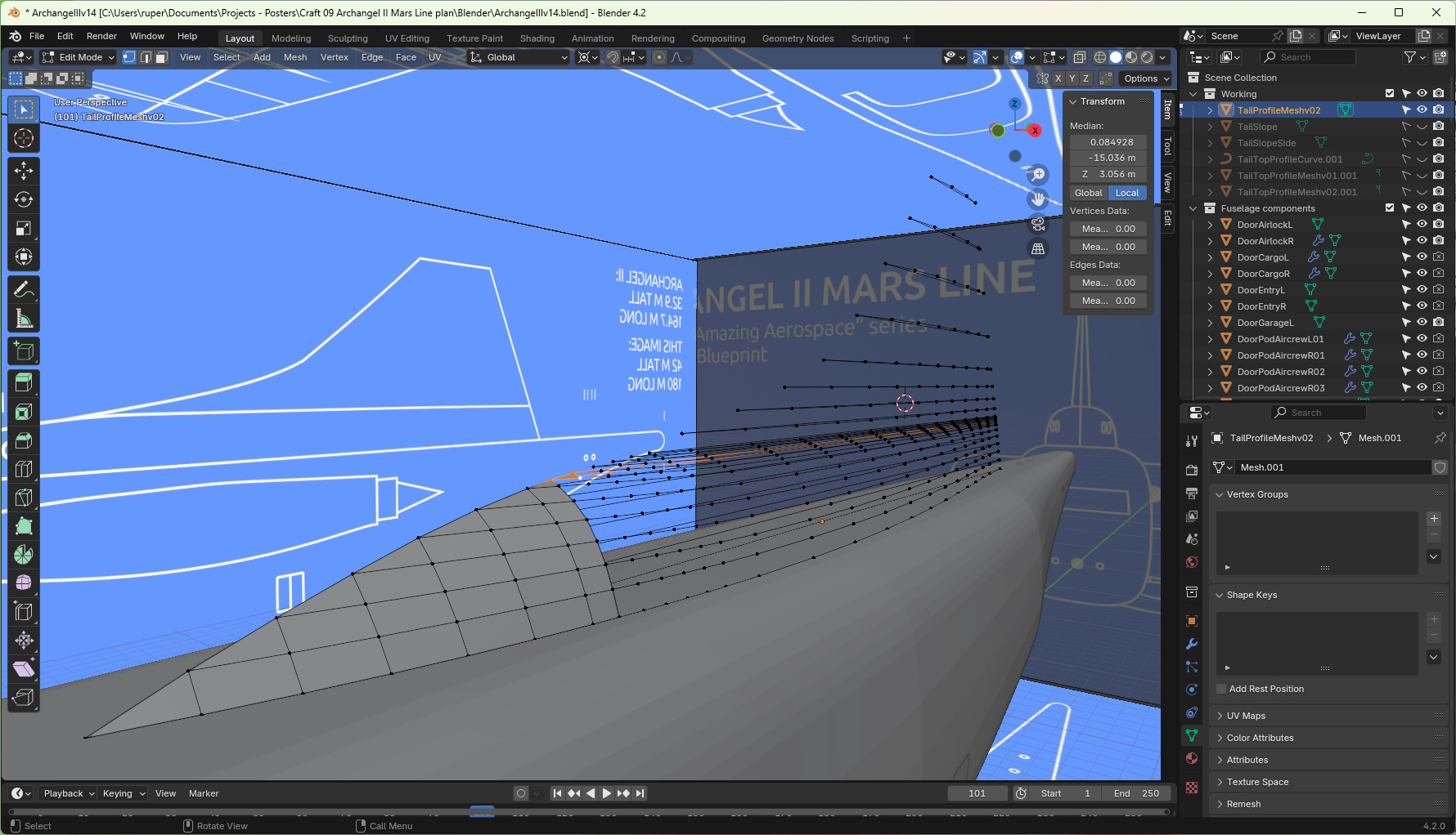
Below is the vertical stabiliser complete after a mirroring operation.
Ion Engines
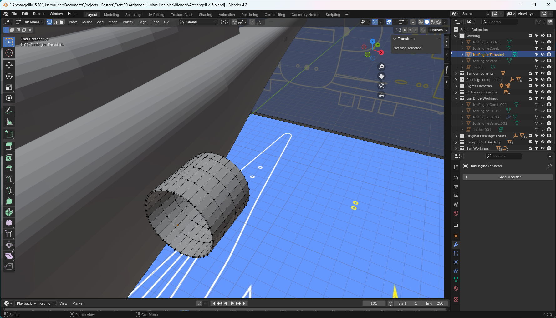
The hybrid "in-transition" nature of Archangel II's technology means that it relies on air breathing jet engines to get it to the edge of Earth's atmosphere, before it fires up the ion engines for the journey to Mars. I'm also making the assumption that it is not a good idea to release super-heated ion plasma into Earth's atmosphere. Two tokamaks inside the tail produce the energy for the ion drive engines, thus the need for the engine housings to be attached to the fuselage in that way.
I start with the outer ion plasma guide.
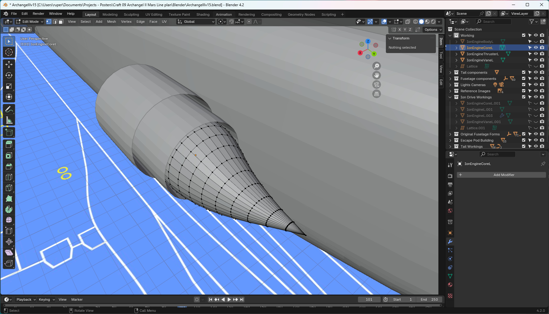
The plasma vents between the outer guide and the central cone shown below. I put a twist in that cone based on the assumption that the plasma vent would come out of the tokamak not only super hot, but also spinning very fast. The idea is that the twist aligns the plasma jet with the ship. Who knows - I think it looks quite good that way though.
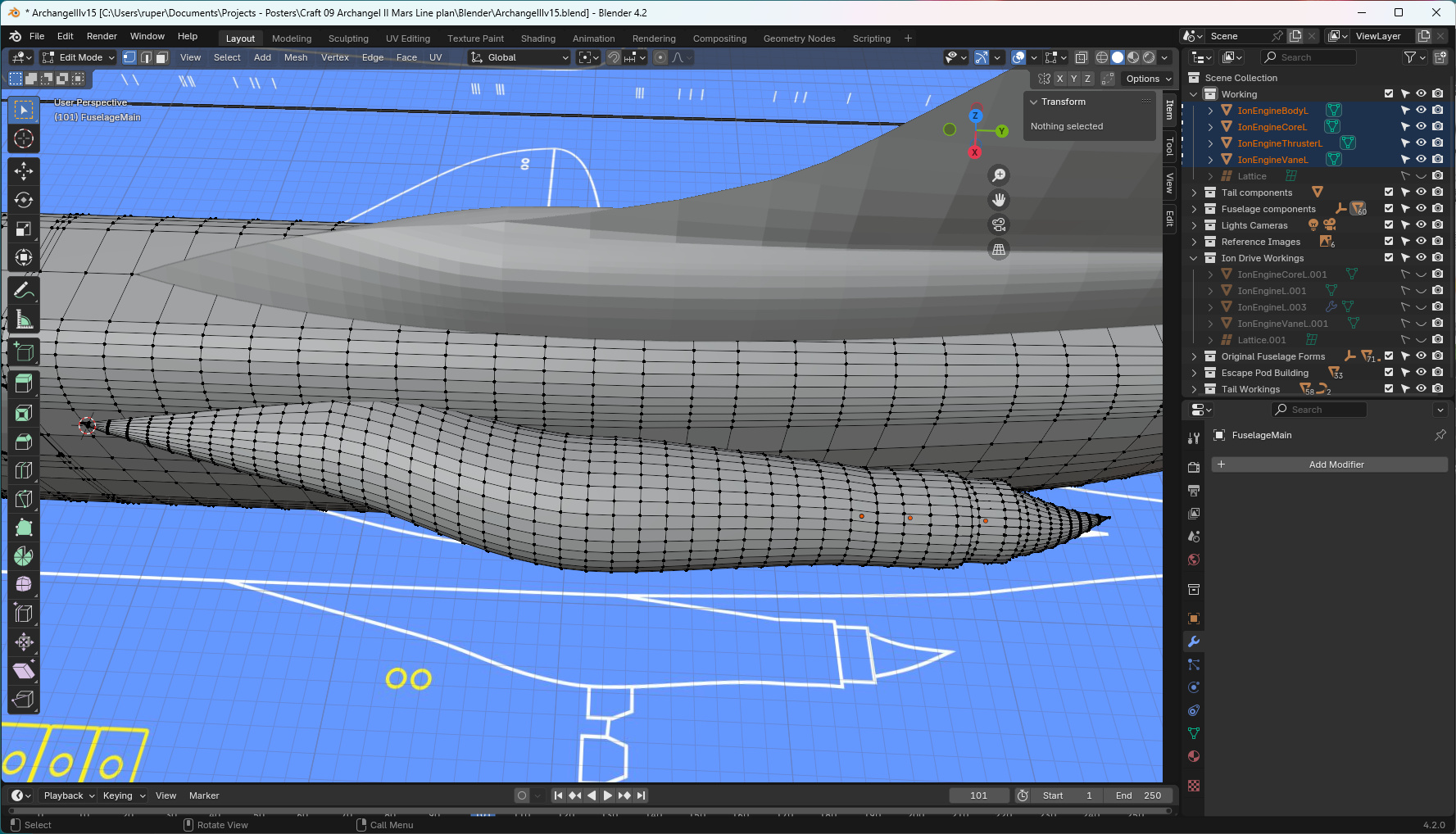
The image below shows the full ion engine structure and its relationship with the fuselage. I like the fact that the engine is slightly "gangly" and awkward. It speaks again to the transitional nature of this design.
Flying surfaces
The word "ogive" represents the smooth way in which a shape tapers to a point. For Archangel II, I have basically pinched Concorde's beautiful ogival wing for two reasons - it's a fantastic shape, and Archangel II would be many times supersonic by the time it left Earth's atmosphere.
I've given Archangel II canards because it feels right that such a large ship would need those additional control surfaces. Concorde never needed canards but it was given a discreet set of vanes. There are other good examples of aircraft with canards: Viggen, Gripen, Eurofighter, Rafale, Piaggio P180 and the mighty XB-70 to name a few.
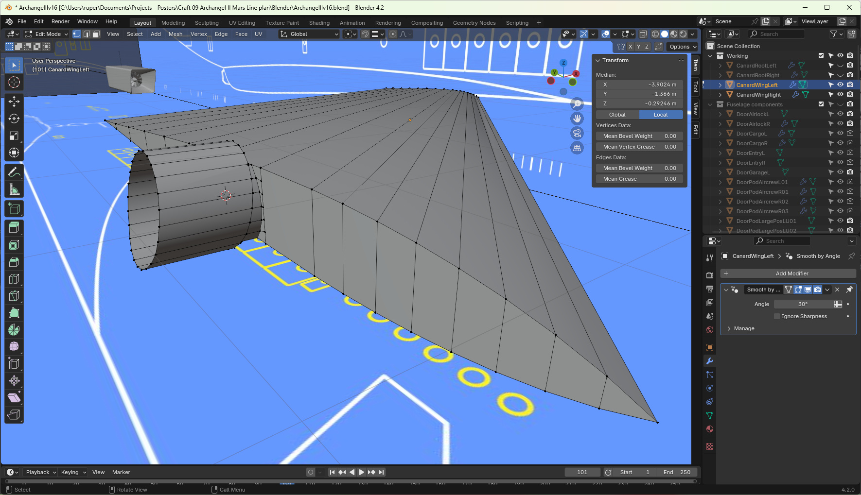
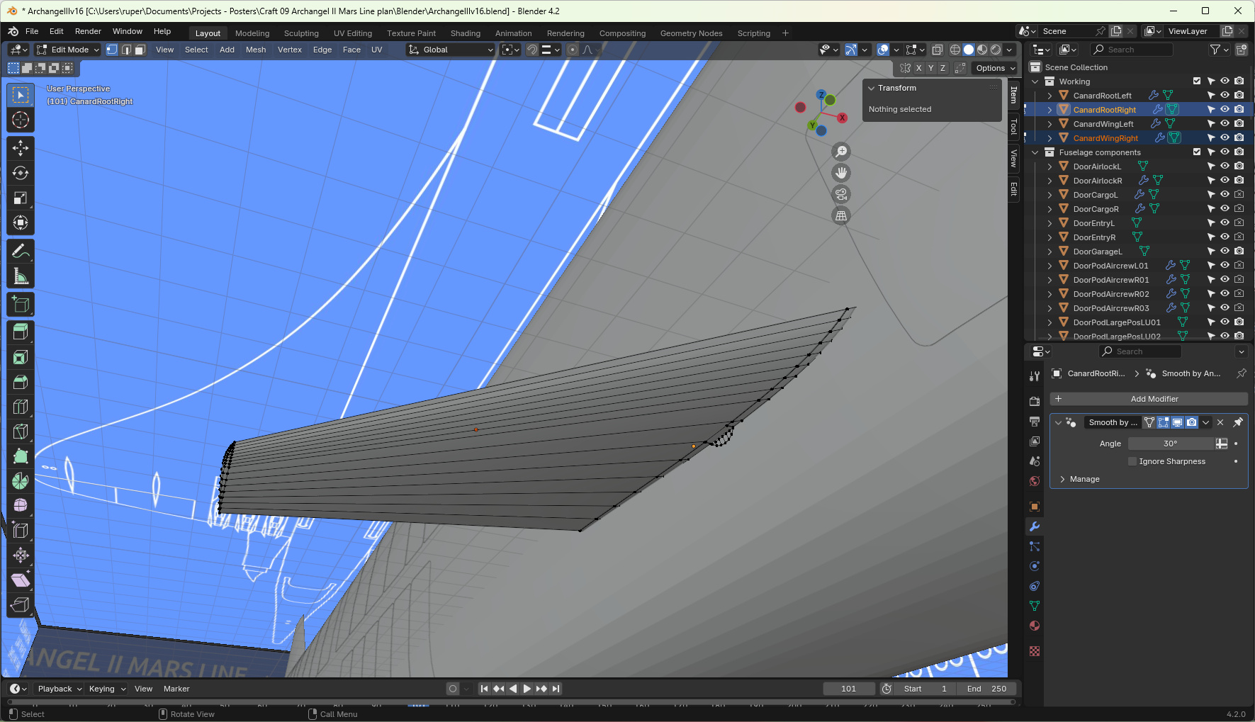
The only fiddly thing about the canards is how they attach to the fuselage. If the whole canard is a movable flying surface, you have to design it so that when the canard does move, it doesn't grate along the edge of the fuselage. In Archangel II's case I had to build it a discrete mount.
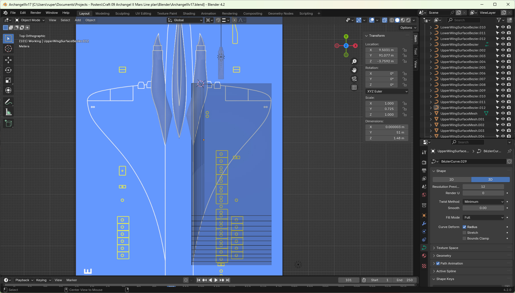
The main wing - I wanted to use my "removing geometry" technique. It took me a little while, and a couple of goes, to figure out how best to do that. I started by assuming that each wing section would be created using a mesh profile with a reducing number of equally spaced vertices. The image below shows how I defined the size and position of each wing section.
The technique I developed was to use bezier curves - define the profile I wanted and then copy and scale bezier curves to create the set of wing sections.
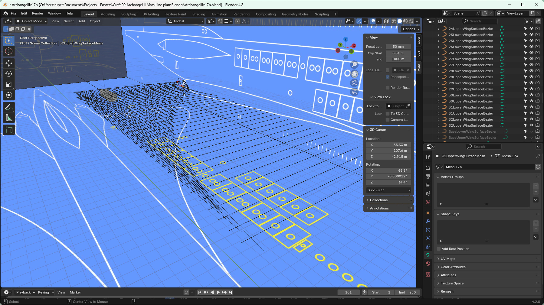
Once I had my set of bezier curves, I simply converted them to meshes, each time reducing the vertex count by one, and then using loop tools > space to make sure the vertices were evenly spaced along each profile.
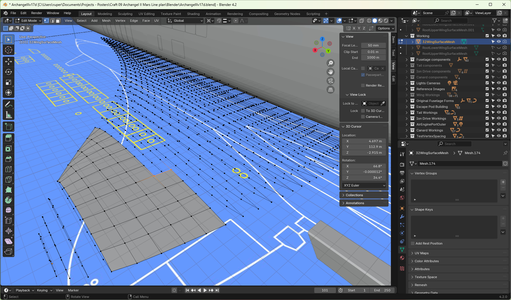
There is a very cute trick for quickly filling in faces in this kind of mesh. You select the vertices of the first face to be filled and press F. Then select two vertices in the direction you want to create faces - and simply keep pressing enter. It works well.
At this stage my wing profile shows an even thickness along its length, but real wings taper (get thinner) towards their ends. To thin the wings I used a lattice modifier and then a curve modifier to give it its curved down shape.
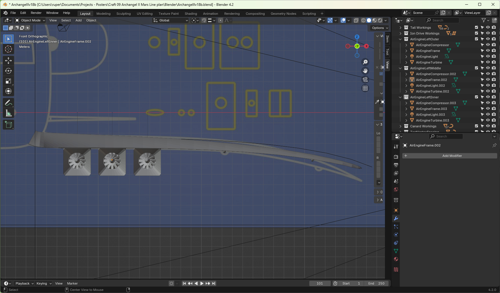
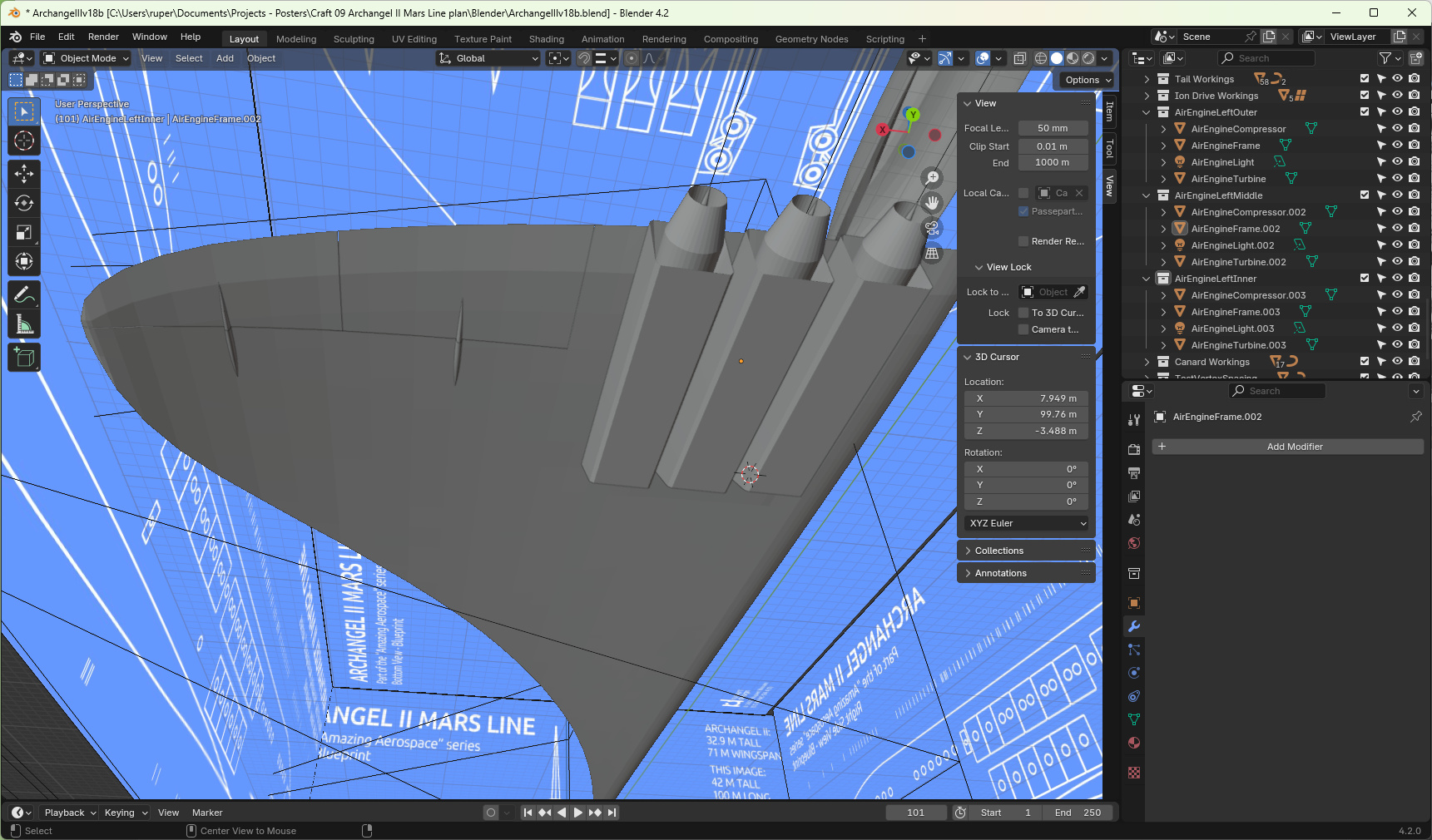
Using principally the knife tool I cut out the control surfaces and gave them a little actuator each.
I kept the air breathing engines pretty simple - basically a box and a hint at jet exhaust. The only complicated part was the front turbine. Starting with basically a cone, I was able to extrude and twist fan blades, as you can see in the image above.
That is the modelling of Archangel II complete.
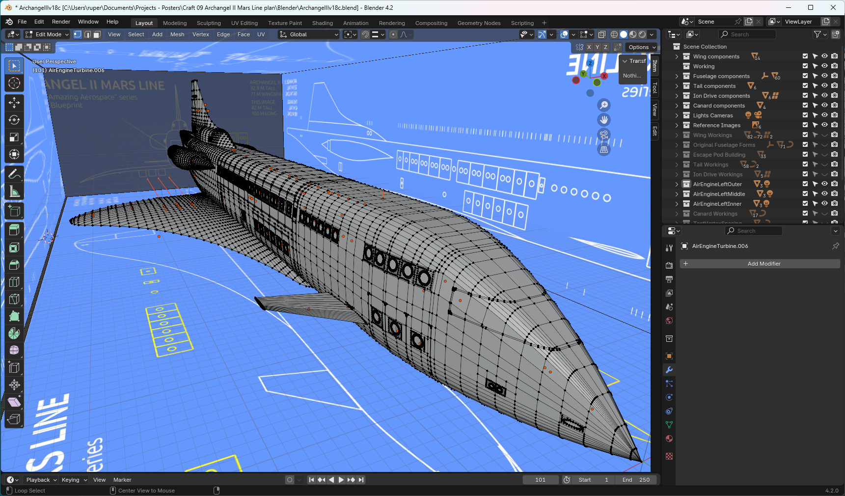
But that is not the end of the story. My main model file is full of building artefacts - things I created along the way but which now do not form part of the final model. The final acts are: to check what is in the final model, make sure parts are named correctly, and everything is in an appropriate collection. Then create an empty and parent everything to that empty so the model as a whole can be moved around by moving a single thing. Then, in this new model blend file, delete everything that isn't part of the model.
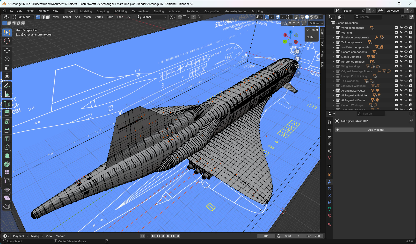
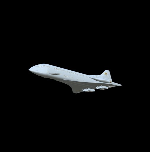
That is the end of the model build. Time to start thinking of some posters. Click on the image below to view the completed 3D model in model-viewer.
Back to top