TARKINE
IN BLENDER
Building the clipper at Cyber-Montaudran
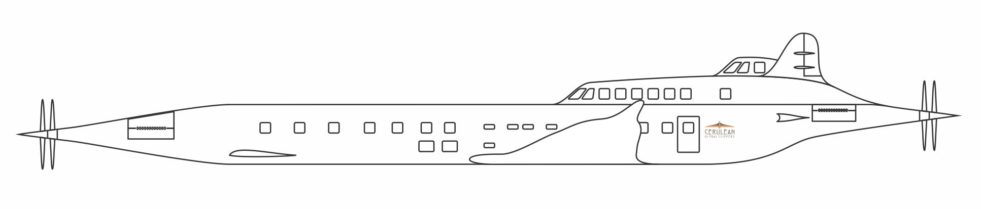
Blueprints
You can use the zip file of blueprints below as reference images in Blender. Reference images act as guides to help you build your models.
Tarkine rising
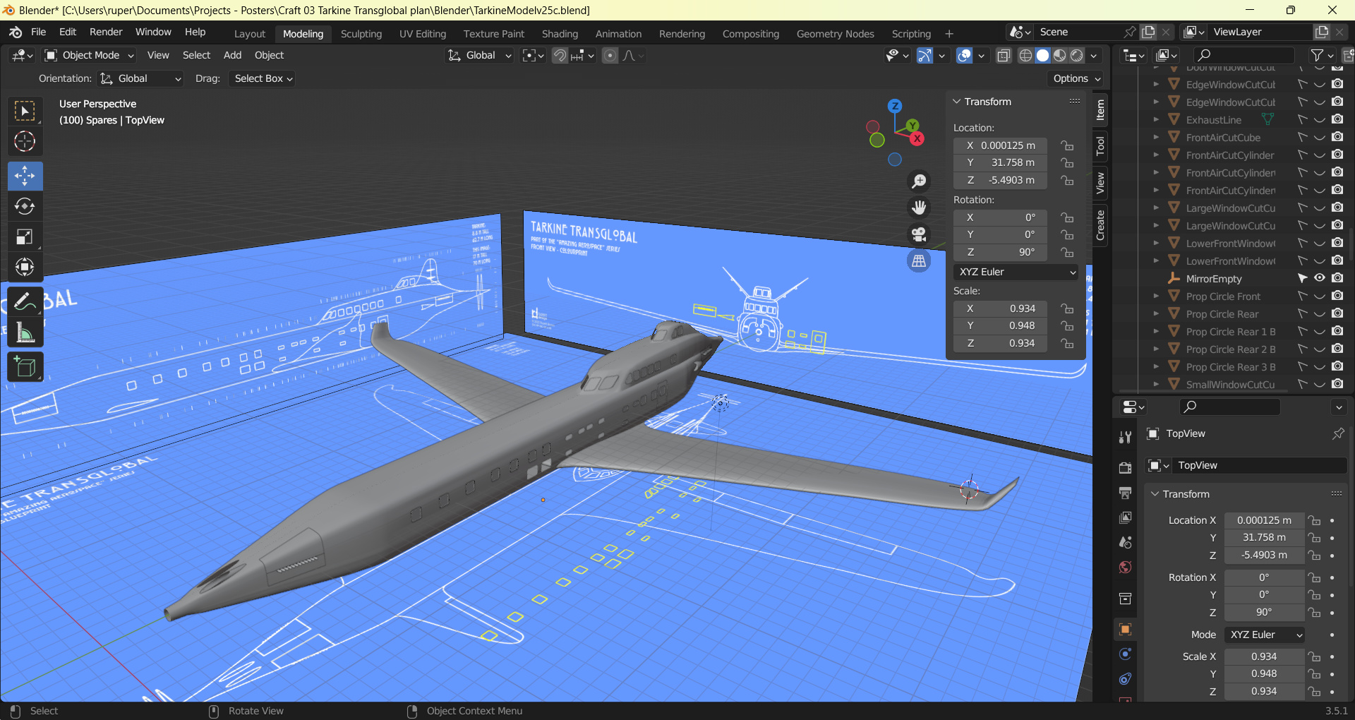
Tarkine Transglobal - the first thing - setting up my reference blueprints.
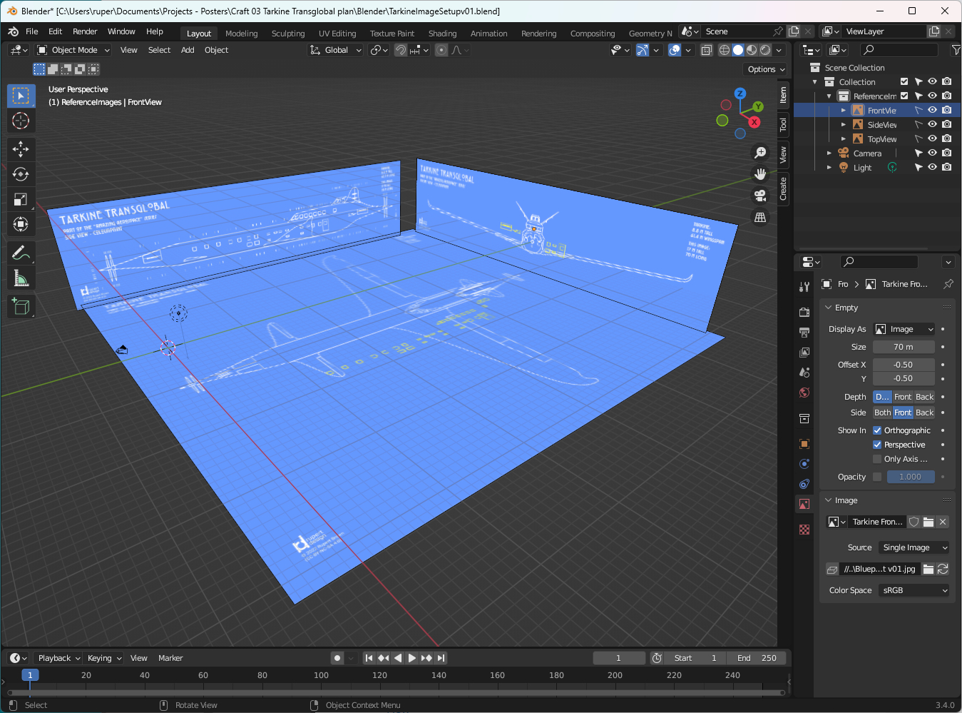
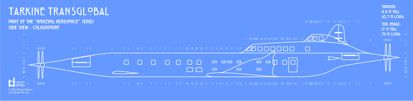
I want to model Tarkine to scale which means making the reference images the right size. To help with this process I write the size the image needs to be in the actual image. You can scale and set these to the "real" size in Blender. Then it is a matter of deciding how the aircraft should be positioned with regards to the axes. I've put Tarkine's nose at the 0 0 0 origin, and the fuselage along the Y axis.
Tarkine - on the shop floor of Cyber-Montaudran
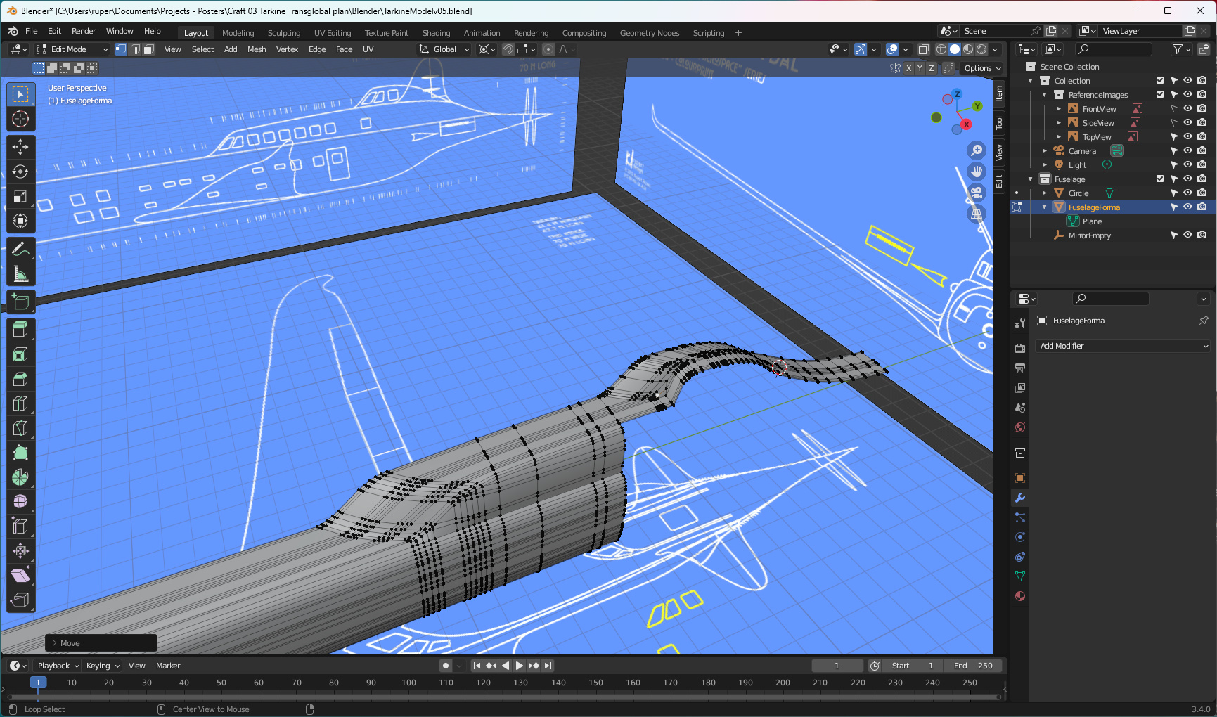
When modelling using Blender, I believe one of the most important things is working out how you will start your model. Blender is very powerful and will let you make any number of adjustments to the geometry of a model - but life becomes so much simpler if you get the form of the geometry fundamentally correct from the start.
I've completed Blender courses that tell you to start with a standard mesh that most closely resembles the final shape you want to achieve. I think that is good advice, especially if you are relatively new to the tool and still finding your way. With experience you can start in a more design-driven way. The fuselage itself is a squared off tube, but that in turn is complicated by the need to create windows and the wings of course. I developed Tarkine's fuselage cross-section by extruding a single vertex from a plane following the blueprint, and then deleting the plane.
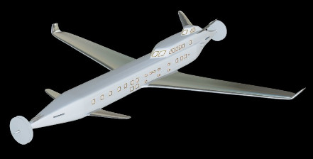
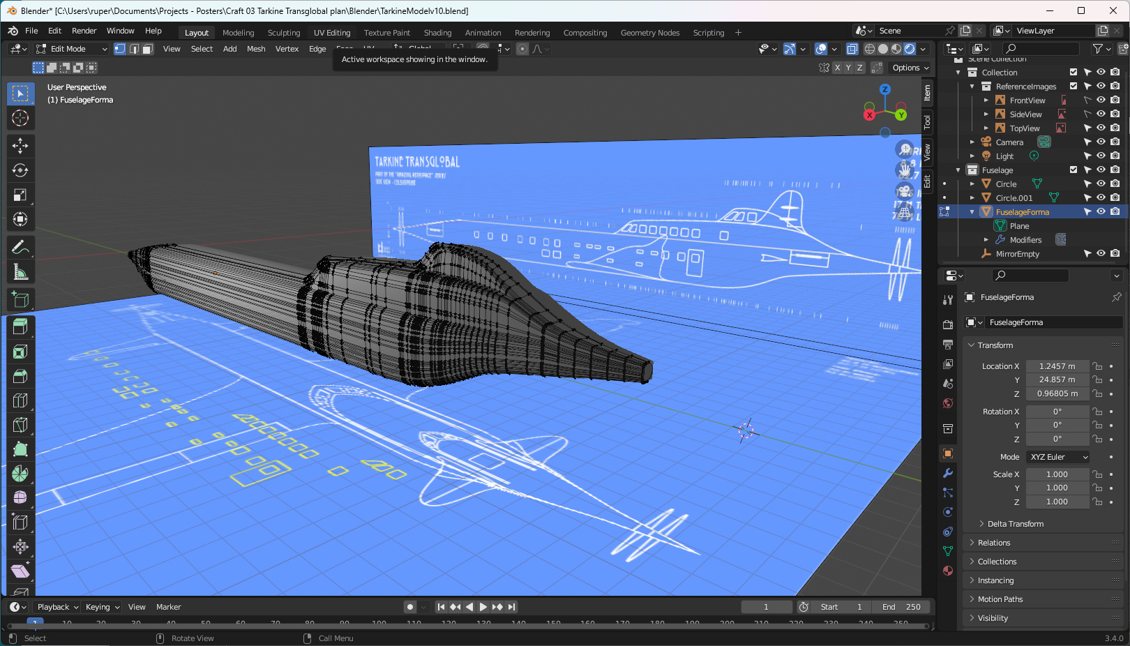
I knew that Tarkine was going to be quite a complicated model. You just have to look at the configuration of the rear of the fuselage to see that. That shape which ends up as a fusion of the fuselage and Sky Lounge and Pilots' cupolas is quite unusual.
So before you start modelling, I think it is important to ask yourself two questions:
- For this model, how should I create the mesh? Is the model going to be one large mesh, or is it better to divide things up and create model parts from several meshes?
- For each mesh, how do I create the geometry to support the features of that part of the model?
In the case of Tarkine I've taken the decision (right or wrong) to create the following parts list:
- Fuselage,
- Main wings,
- Canards,
- Tail fins,
- Propellors,
- Engine exhausts.
In terms of the fuselage mesh, I've included geometry I hope to be able to use to create windows. I'm quite pleased with the way it is developing, and how my blueprints are working out. Long way to go but a good start.
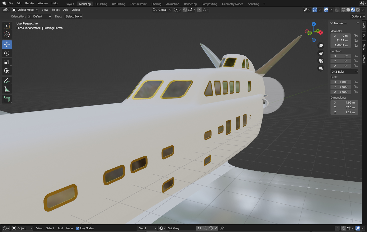
Tarkine - window geometry
To be honest, my cunning geometry plan for Tarkine was only partially successful. I had laid down geometry which I thought would support me easily building the windows and doors - but it didn't turn out quite that way.
The problem I faced was that I wanted all the windows and doors to be of a consistent form, even if they are different sizes and shapes. This led to a lot of head scratching about the way to create those shapes. In the end I decided to create the templates I wanted as mesh shapes, and then create the geometry using the boolean modifier. A great plan but - doing that creates geometry which could be described as messy or at least non-optimal.
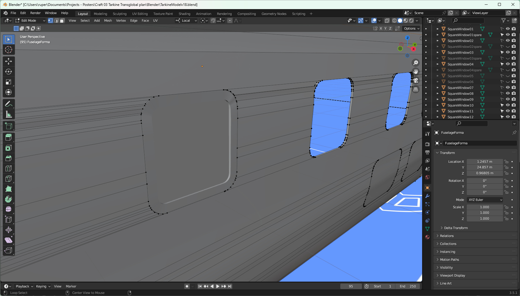
You can see here that creating the window opening has created more complex geometry around the opening. I've gone back in and manually fixed up things which I believe makes it better. But it is time consuming. I'll have to think again about that whole process.
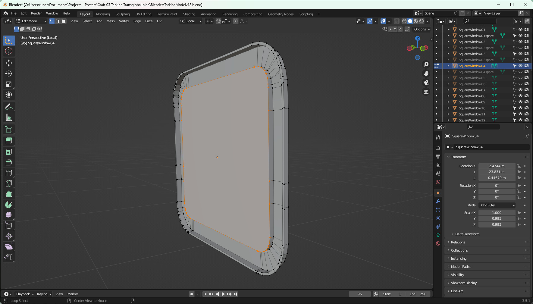
I'm actually quite pleased with the windows themselves. They took a bit of moving, scaling, deleting and extruding along normals and local axes, but the result gives me the geometry I wanted. That is driven by my plan for the application of textures.
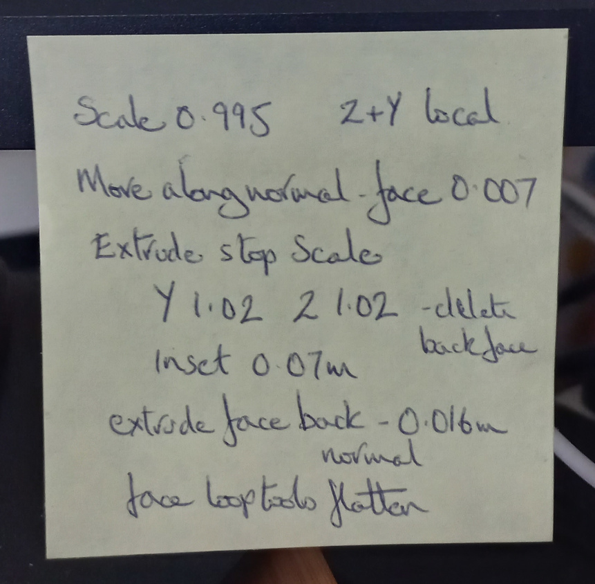
Engines
Tarkine has four large engines - two at the front and two at the back. The design makes these accessible from outside and inside the aircraft. Access from the outside requires that Tarkine has access panels, and the engines need exhausts.
Once I was happy with the overall shape of the fuselage, I used the Solidifier modifier to give the fuselage mesh a little thickness - roughly around 10 cm. To create the engine access panels I used the knife tool to cut the shapes, then with the outside facing panels hidden, fixed up the geometry to create the inside. It is important to check the orientation of the surface normals when doing this kind of work. The inside will be important because it will be a different colour (black) that will be visible around the exhausts.
The exhaust shape is a separate mesh duplicated twelve times, one for each cylinder. The exhausts will have a different texture - a kind of dirty steel.
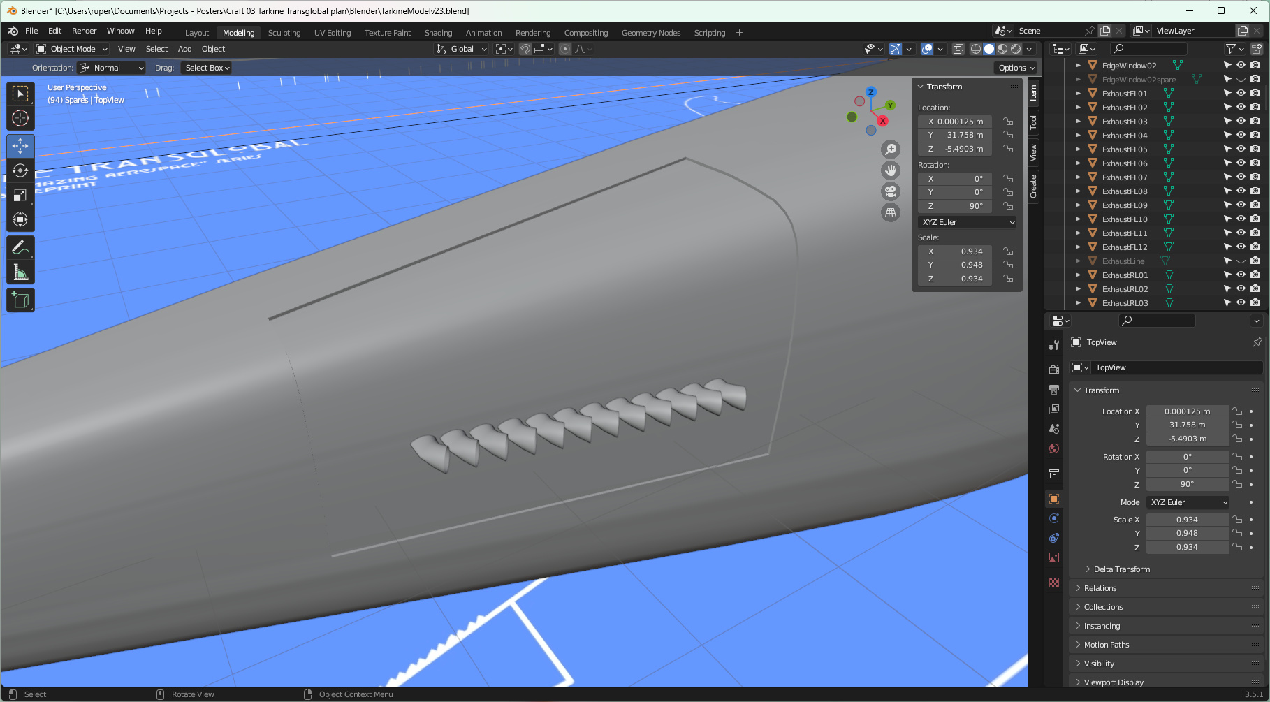
Wings
A wing is always a beautiful object to model. A wing has curves that need just the right level of mesh geometry to be properly realised. Tarkine's wing is a slender, graceful affair. As you can see from the image, where the curves are "tighter" I've applied more geometry.
The building process is to define the principal aerofoil shape and then extrude and scale that shape to create the wing. Even though the aerofoil shape may not appear to need it, it is always a good idea to have the same number of vertices on the top and bottom surfaces. This makes it much easier and neater to close out the mesh once you reach the end of the wing. I gave Tarkine some winglets. Winglets help to stop the low pressure zone on the top of the wing from 'slipping off' and so improves aerodynamic performance.
I used the knife tool to cut out and create the flying control surfaces - elevators and flaps. The neat trick described below involving orientations lets you build curved surfaces so that control surfaces neatly fit into the main wing.
Tarkine - ailerons
Ailerons, and flying control surfaces in general, are quite tricky. They have to maintain the profile of the wing but be a discrete piece with a distinct line of separation from the wing. In of themselves they are quite easy to make. You model the whole wing, in Edit mode select the part that is going to become the control surface, and then do the Shift d | LMB click | p s thing which does the separation. But then how do you get that gap?
Simply moving vertices in the global X, Y and Z axes is very tricky if you want to maintain that wing profile. I found I was messing things up very quickly. To create the gap, vertices have to be moved along the profile axis, and by a controlled amount. You could do a vertex slide but that has a problem. It won't tell you the absolute distance you have moved your vertex - only the percentage moved (to the next vertex).
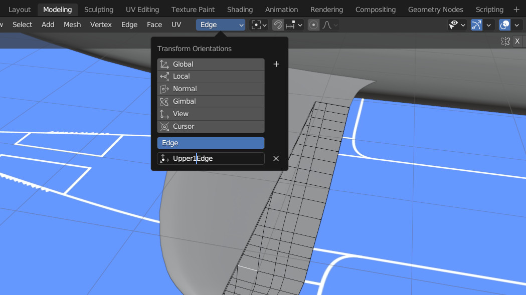
I worked out a very neat solution using custom orientations. Just like the Global - Local - Normal orientations, so you can create your own. Select the piece of geometry you want to orientate to - in my case it was edges on the control surface. Click on the orientations menu, click on the + sign, and give your new orientation a name.
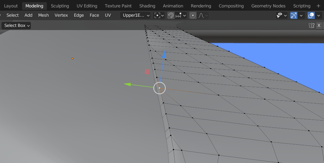
Select the vertex you want to move, press g then use the arrows to make the movement along a particular axis (in this case the green one). The precise extent of the movement you require can be typed into the transform dialog (bottom left on my interface). In this way I was able to create very precise gaps around the control surface whilst still maintaining the wing profile.
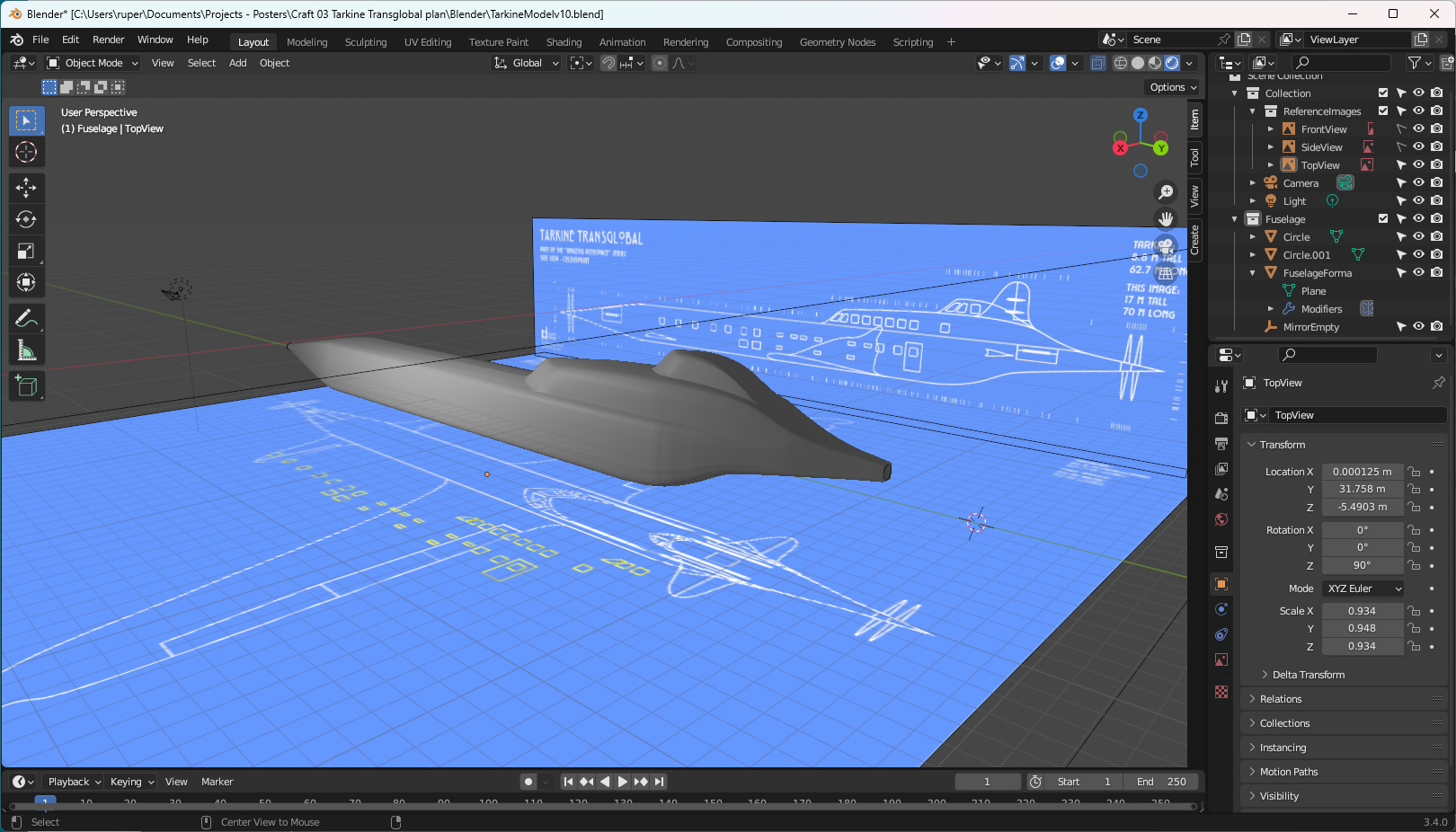
Tarkine is whole
It has taken far longer than I expected, but Tarkine's modelling is pretty much done, and I'm quite pleased with the result. It fits with how I expected the aeroplane to look based on its plan drawings. I have created all the mirror modifiers - I'm just going to check what is there - then I'll apply them all and create the final shapes.
After that it is off to the paint shop for some textures, then a new poster set based on the exploits of the Tarkine Transglobal.
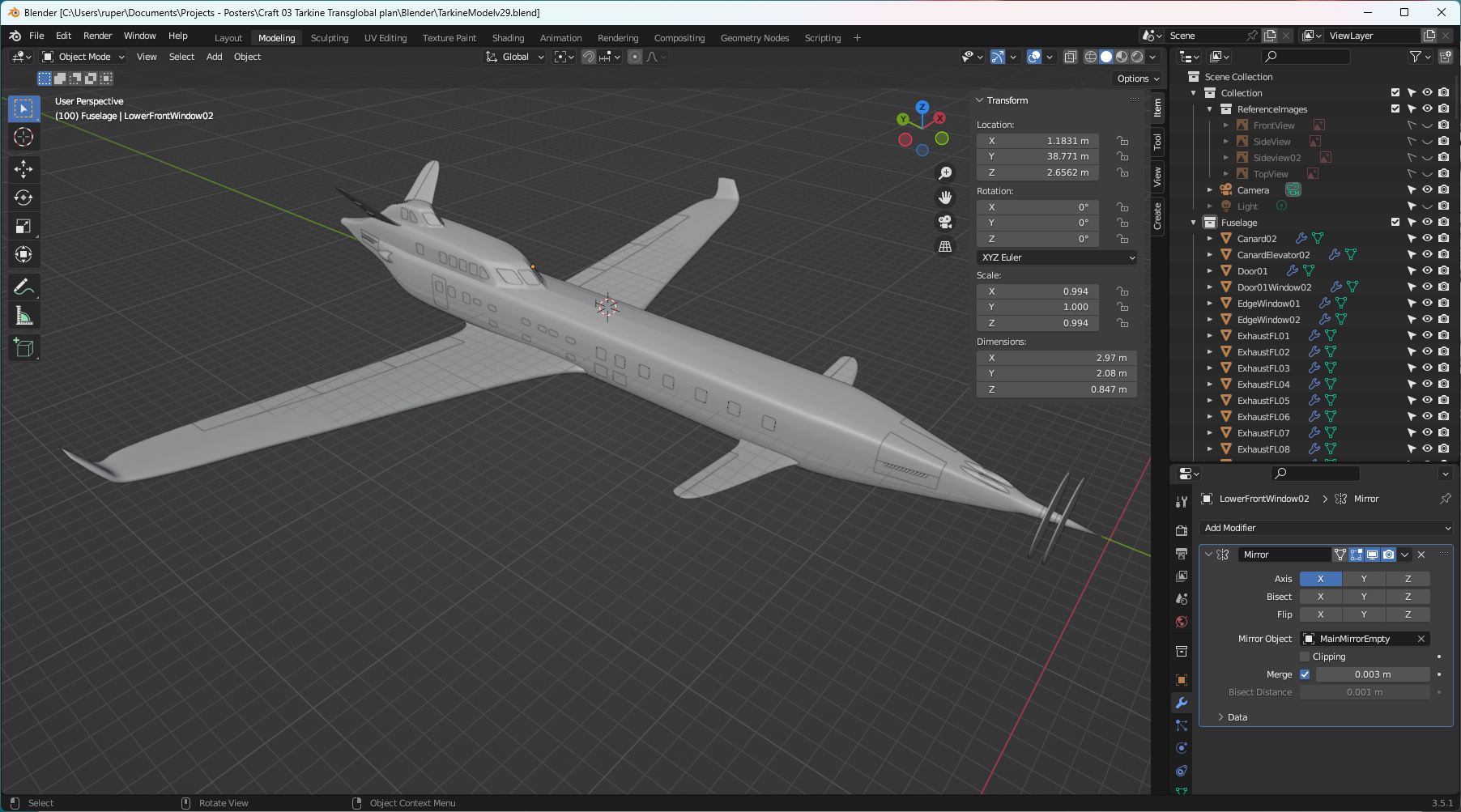
Tarkine - modelling complete
You have to learn to stop fiddling! I applied all the mirror modifiers for Tarkine, and tidied up the file, getting rid of spares and construction pieces. Then you look at it and start noticing little imperfactions - and start fiddling! Anyway, I did smooth out a couple of things that popped up after the mirrors were applied. The skin surface is a bit rough in places but that is OK - aircraft from the 1930s, after a few years of flying, did look a bit battered. They were never perfectly smooth.
Then I produced one of those little spinning videos. The trick I found is to add an empty at the point where you want you model to spin, then parent all the parts of your model to that empty - then set up the rotation on the empty. That way all the parts of your model move in the right way relative to each other. There are many good videos on this - have a look.
Tarkine textures
Because of the style of the posters I want to produce, like Skyluxe, I don't need complex super-realistic textures for Tarkine. I've gone with a very simple palette - a silky white for the fuselage, gold and glass for the windows, shiny stainless steel for the wings and "dirty steel" for the exhausts.
I think Tarkine has turned out well. Onto the next creative challenge - those alternative travel posters that show off the aeroplane and the wonderful things it can do.
Model viewer
Click on the image below to view the completed 3D model in model-viewer.