Archive 02
Planning a second Aircat travel poster
18 February 2024
I wanted to do something different with the second Aircat poster - to introduce a human figure. As usual there are a huge number of options and all of them have different costs and implications. DAZ3D have a whole ecosystem of characters, clothes and props and something called the Daz to Blender bridge. That looks like a great thing, but too much of a learning curve just at the moment. It turns out there are many places where you can download people models, and a lot are free. I had a vague idea of what I was looking for and in the end found it on 3D People in the form of 10901 Diana.
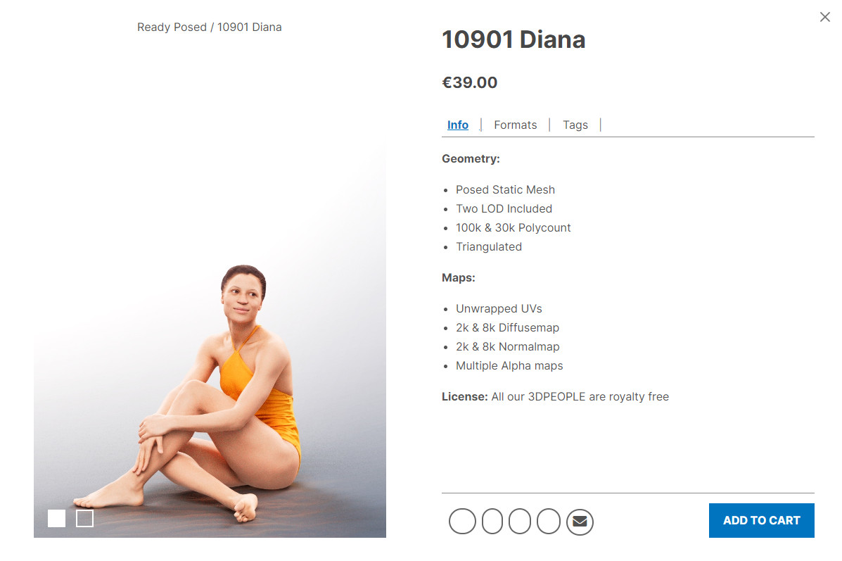
I wanted a good quality model, and from what I could see Diana fitted the bill, but before shelling out €39 (around AU$70) you want to be sure it's all going to work. Well, 3D People let you download a free model to try. I did that and could not get the textures to work. But at the other end of an e-mail address is a real person that sorted out my problem - all good.
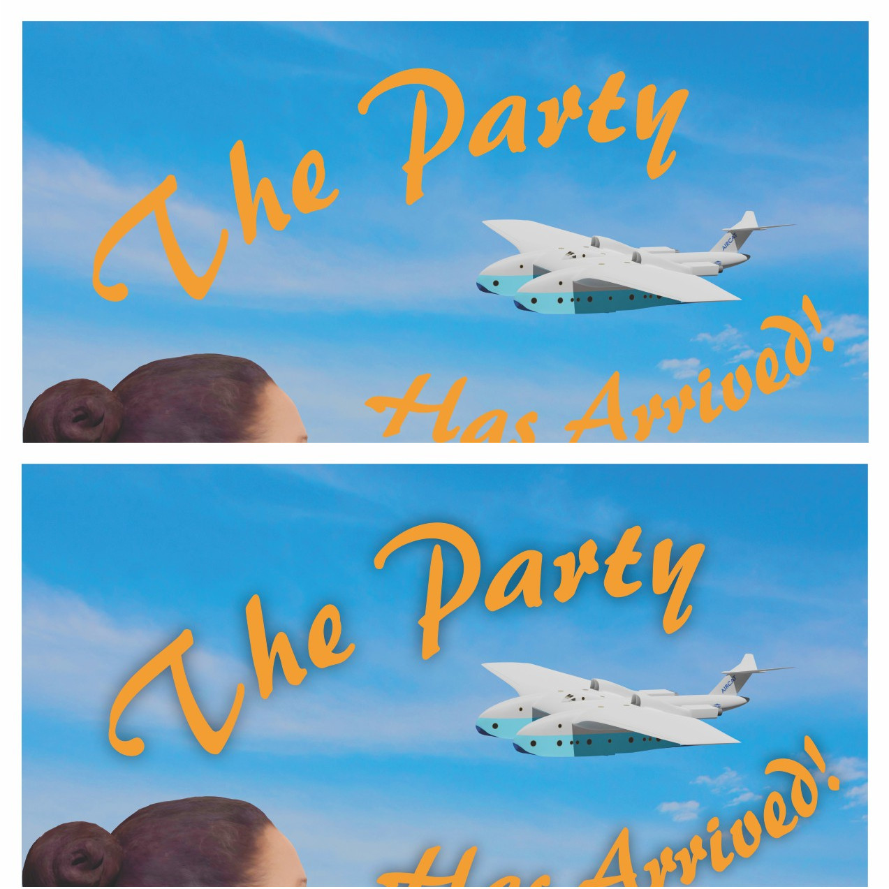
The next challenge was to do a bit of planning to reassure myself the scene I had in mind was going to work. So I did a series of mock-ups using a graphics program. It was all very rough and ready, but was enough to convince myself it was possible.
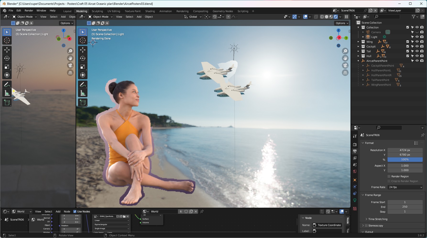
I handed over my cash and started to create the scene. I tried to use an HDRI as a background, but nothing looked right. I could not get everything where I needed it to be. So I changed tack and used an image for a background. The image was from that great resource Pexels but using it turned out to be another challenge. There are lots of great resources out there on the internet so I won't give the detail here - but basically you have to tell the camera you want to use a background image, and tell it where it is. Then you have to use some nodes in the compositor - something I'd never tried before. The image below will give you a clue.
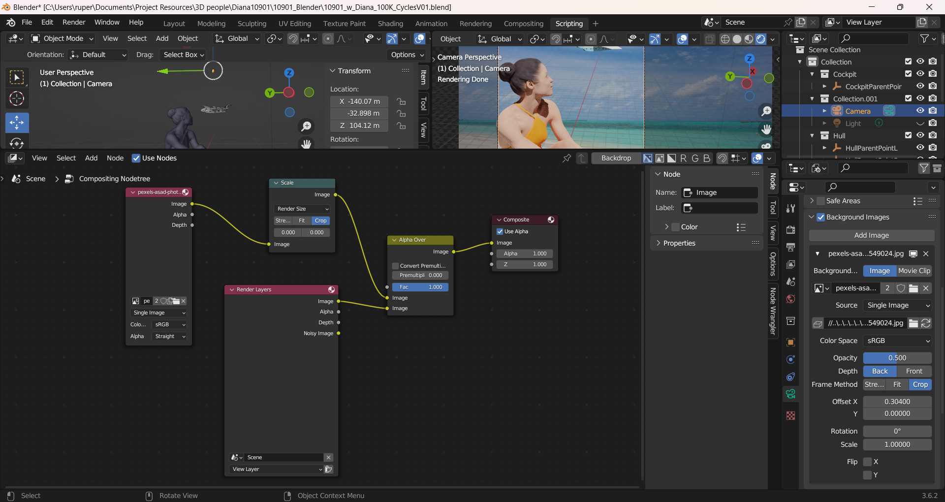
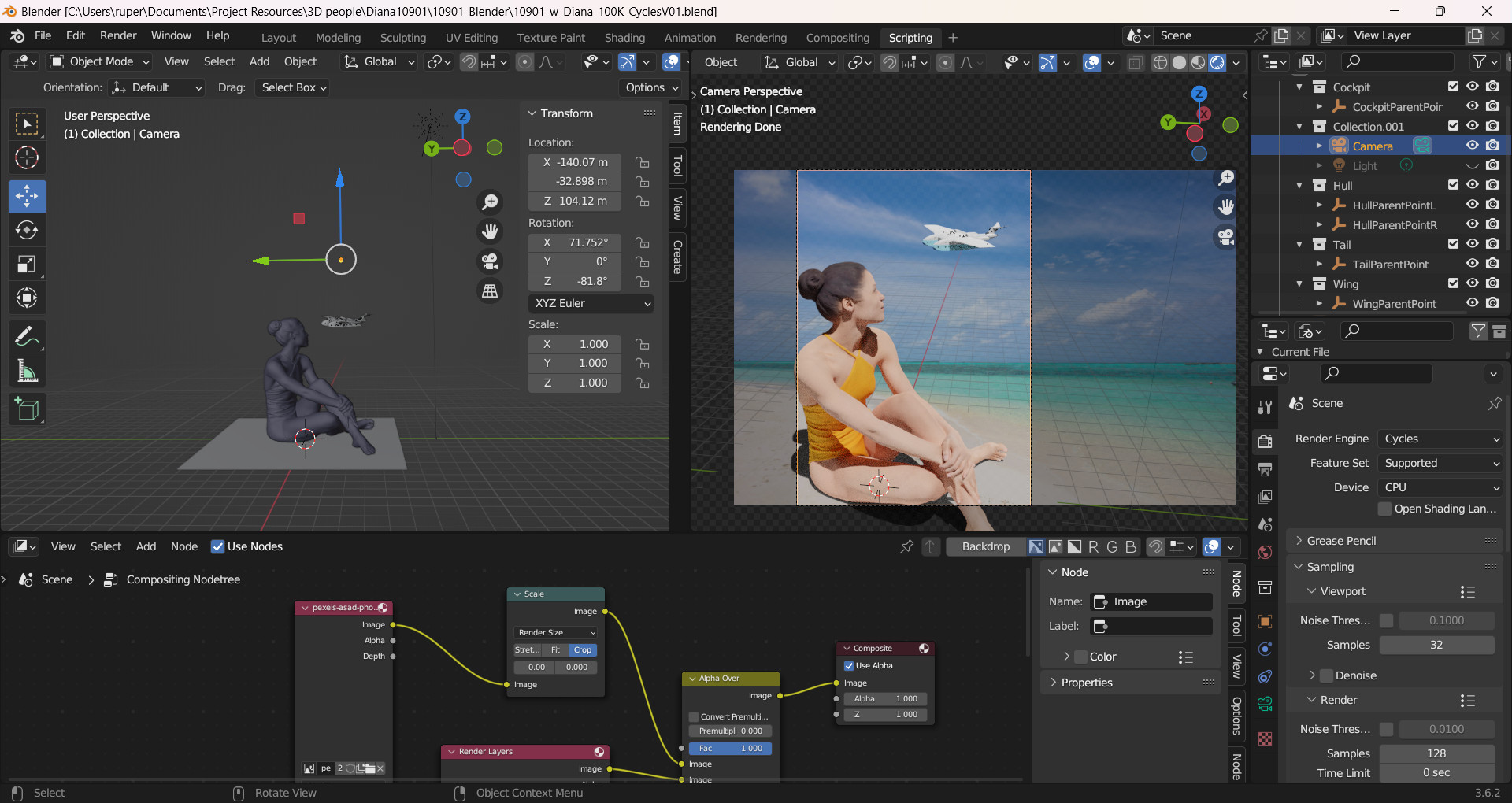
Once I had mastered that trick, the job was the usual struggle with cameras and lights. I wanted a large render (1,000s of pixels). It took three goes - each attempt was several hours long. Makes me think I really do need a bigger PC. This was the way I set up Blender to do the work.
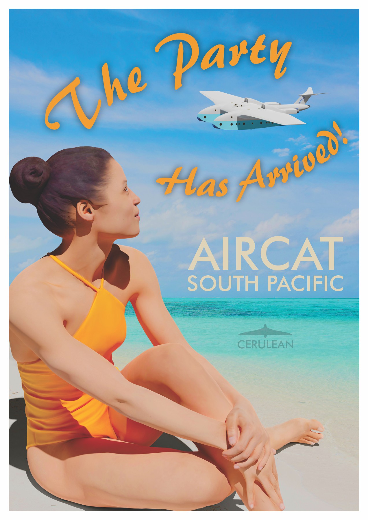
Once I had the render I did some processing to saturate the colours a little and add a bit of 'vibrance'. I put it into my graphics software and started to create the poster. I wanted to keep it simple - with a minimal amout of text. There are a million things you can do at this stage. For the headline text I picked out the colour of Diana's swimsuit. I thought that was a good contrast against the blue sky. It looked flat - so I tweaked it just a bit with a drop shadow. That made a big difference.
And finally here is the poster as it currently stands. I'll look at it for a week or two before making final adjustments. Hello Diana!
A first Aircat travel poster
28 January 2024
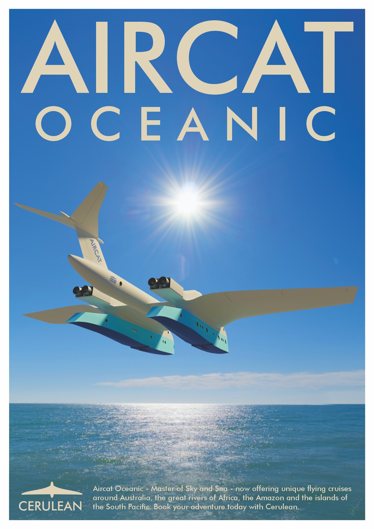
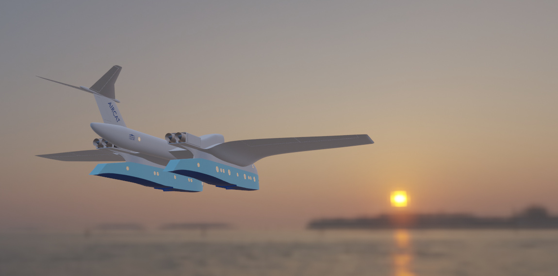
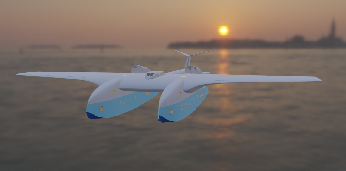
Here it is - my first Aircat travel poster. I've intentionally left it clean and simple. The emphasis is on showing some of the unique forms of Aircat in its two natural environments - sea and sky.
French avant-garde
1 February 2024
It's OK to create art and not like what you produce. In fact it is a very necessary part of the process in deciding what you think is good and bad art - given that such a thing is possible. Many years ago I painted a small picture called 'Flame Tree'. I didn't think it was very good at the time but I kept it for years. I was looking at it recently and decided it wasn't acceptable for me to keep it. It embodied some unpleasant memories and certainly didn't bring me any joy. So what to do?
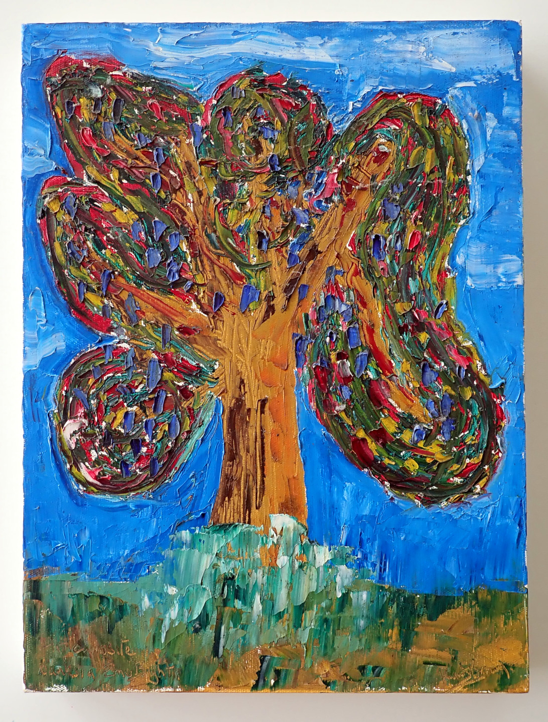
I know I've seen many examples of this - Banksy's shredder being a recent example - you can create an art work by destroying a piece of art. My picture is called the Flame Tree - what better thing to do than burn it? So that is what I did.
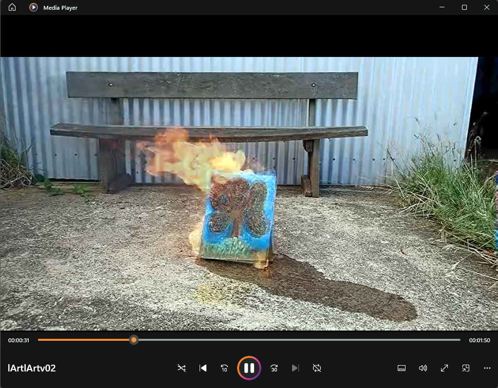
I recorded the whole thing and then used a simple video editing program to produce the result below. Flame Tree, the oil painting is no more, but the Destruction of Flame Tree lives on in digital form. And just for fun I went all Frenchy in the process. Shame I didn't have any Gauloises and Absinthe. Mind you, if I had I probably would not have stopped at one painting ...
A first Aircat poster
24 January 2024
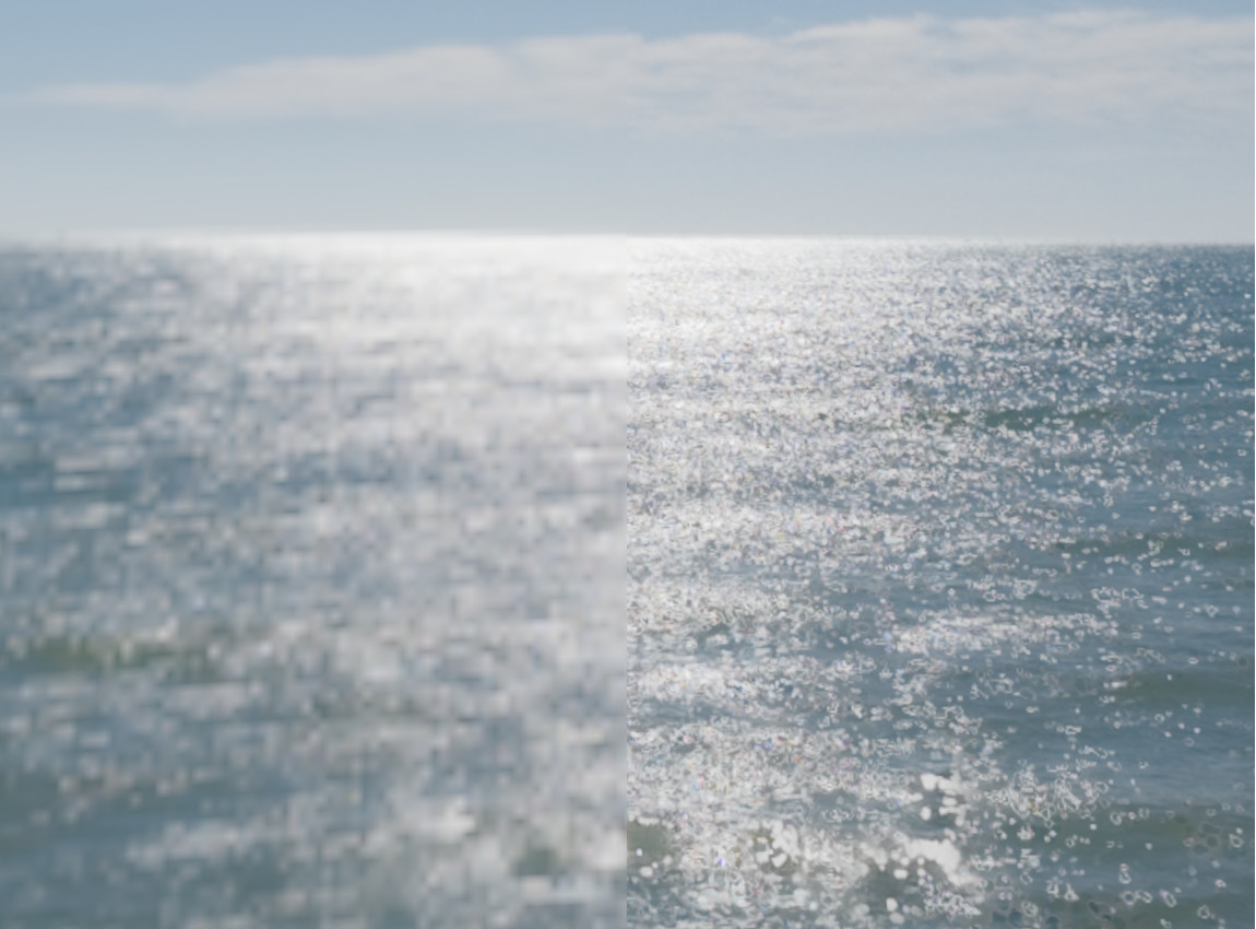
I have been working away on the first Aircat travel poster. I was following the proof-of-concept ideas and testing different HDRI files. I found a great candidate at openfootage. That was giving me good results but in the large renders Aircat was in focus and the sunlight reflecting off the ocean definitely wasn't. There was no problem as such - the free HDRI just isn't that high resolution. So I paid my AUD$13 and bought the high resolution version. The difference is quite dramatic and the results much better. In the image below the left side is the free low res version, the right side the $13 high res version.
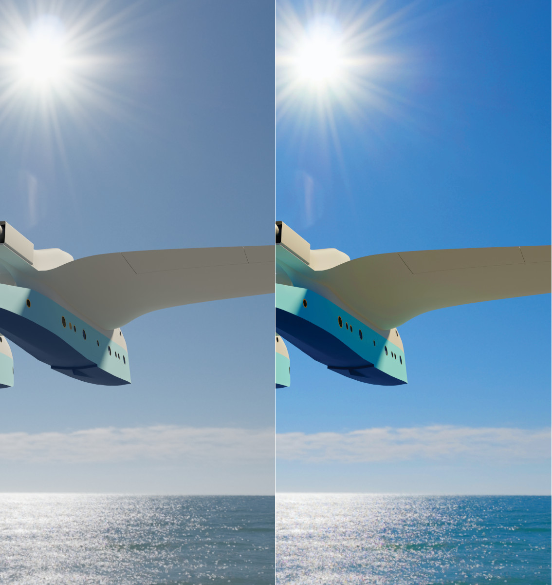
I always find I need to adjust colour, saturation, brightness and contrast to get an image ready for printing. The image below shows the effect of those adjustments for Aircat.
Flow and gilt
21 January 2024
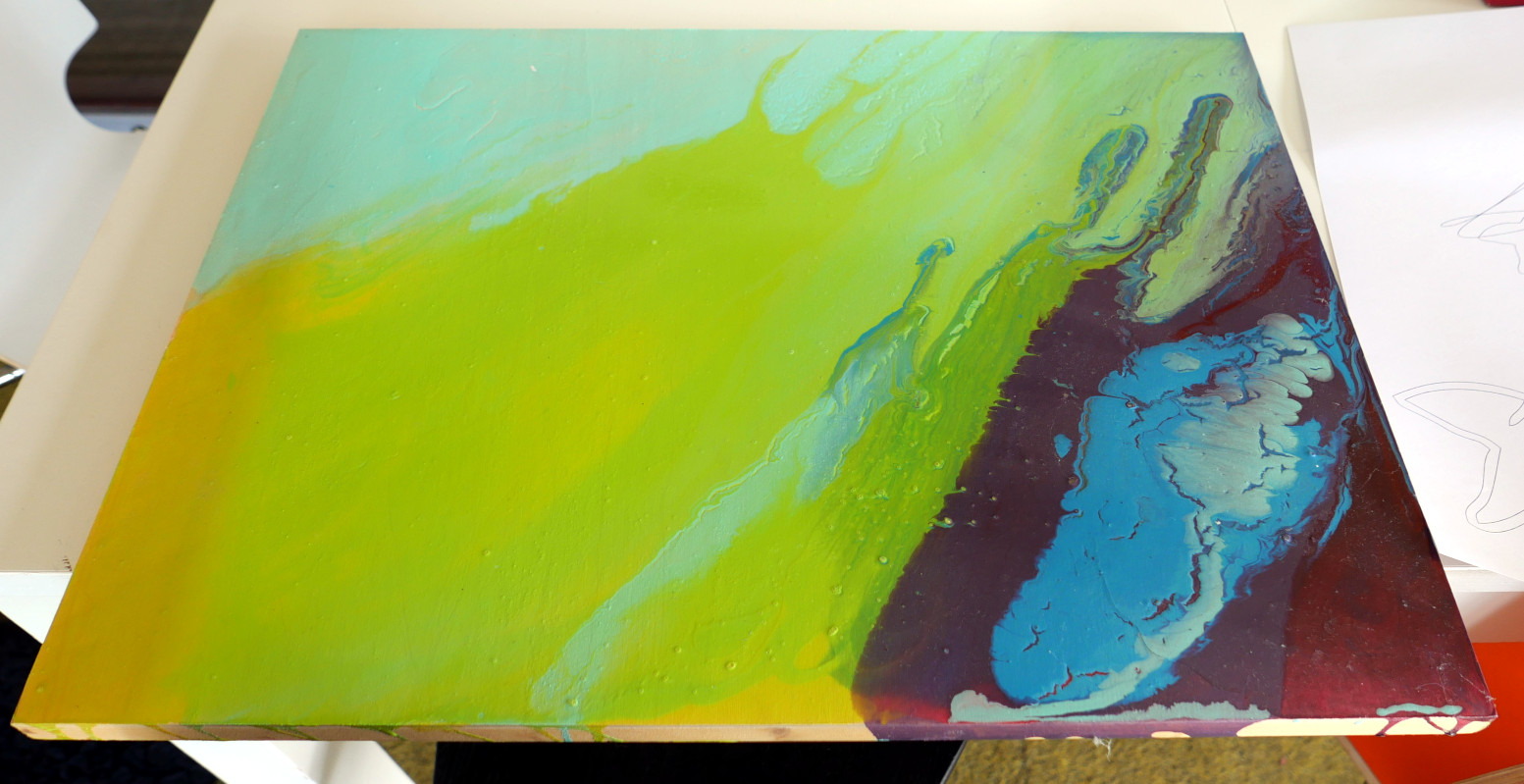
A while ago a family member was trying out flow art - that technique where you use gloss liquid paints to create dramatic colourscapes. She left one lying around and I had been thinking about it for a while. I liked the colour scheme. To me it looked marine with possibly some mysterious 'deeper' sections. I felt I could play around with it a bit and for some reason came up with the idea of 'golden whales' - inspired by the marine vibe? I'm not sure.
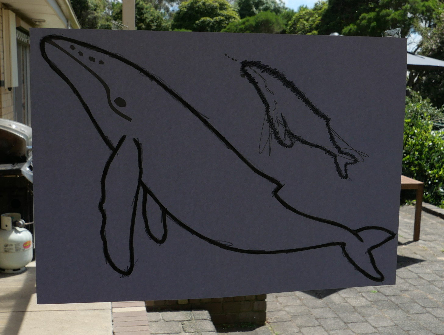
The first thing I needed was a whale image. There are millions on the internet. I used a drawing package to trace a basic outline and then tweaked it to get it how I wanted. I printed the image on A3 paper and then did my tracing trick. On the opposite side of the print to the one you want to see, add a good layer of pencil lead to the paper following the whale outline. Then put that side down on the painting, hold in place with sticky tape, then draw (press on) the outline of the image to be transferred. When you lift up the paper, you have your tracing transferred to the picture.
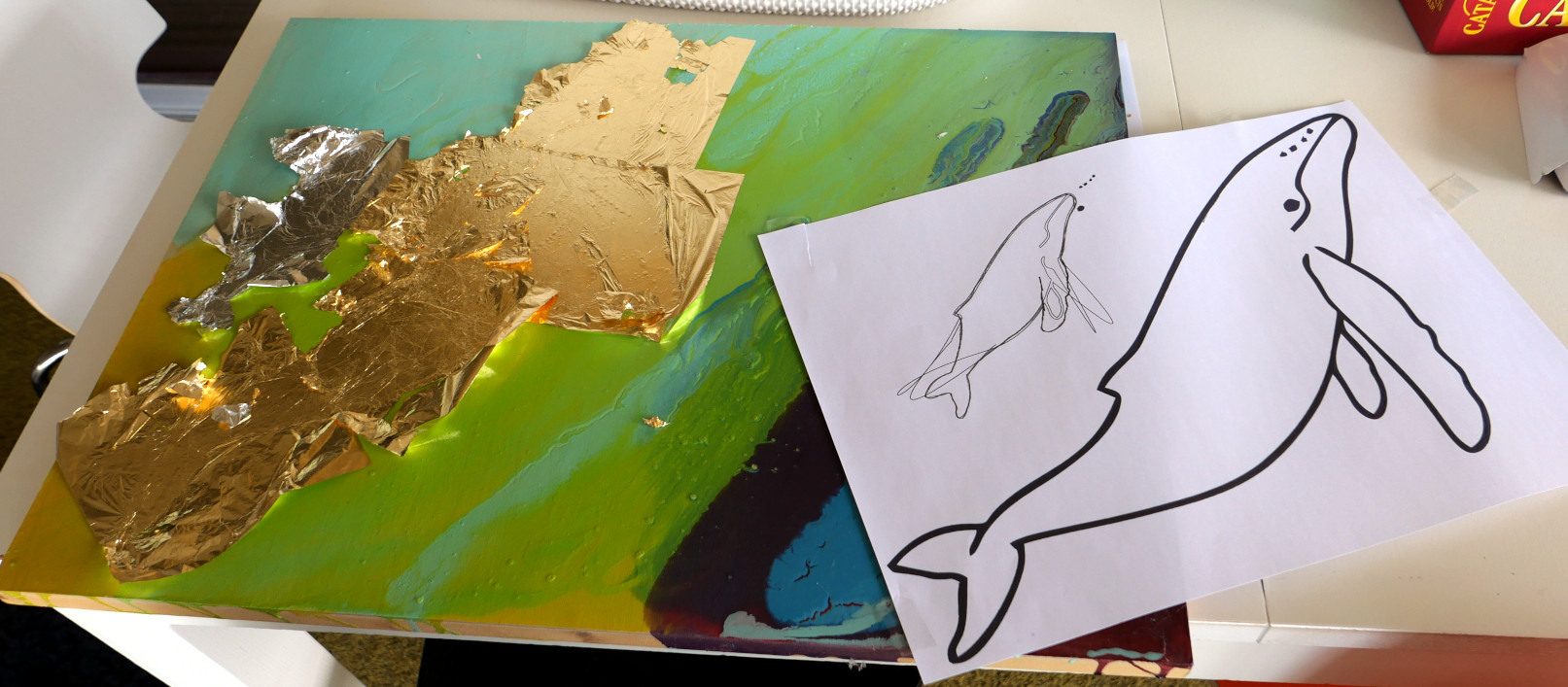
I bought Peboe gold and silver leaves - it's not real gold and silver but looks pretty good. I also got hold of X-PressIt gold size. I don't know if these are particularly good brands but it all worked out well. The process now is to get a brush and fill the whale shape with liquid size following the tracing. Fill the space - anywhere there is size, the leaf will stick. Leave the size for ten minutes to cure. Get your leaf ready.
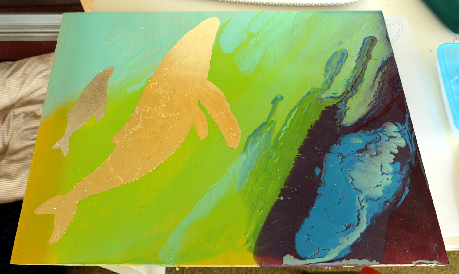
The leaf is incredibly delicate. Best to use tweezers to hold two edges and make sure there are no draughts or air movements in your work room. As best you can, lay a leaf across the area you have painted with size. Do that again till the whole area is covered - you will end up wasting some leaf. Then cover the leaf with a piece of paper and gently but firmly press the leaf to the painting. Now leave it for ten to twelve hours.
After that twelve hours the leaf should be solidly stuck to the size to the picture. The trick now is to get rid of the leaf that isn't stuck. The best way I have found is to use a large bristle paint brush and gently brush the non-stuck leaf away. Be gentle and work at it till you get reasonably clean edges.
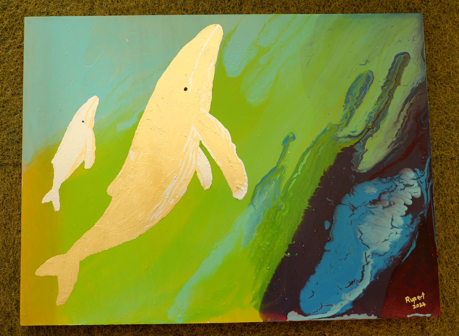
That was all very good. I ended up with a solid gold adult whale and a silver baby but I wanted to add some detail. Humpback whales have quite distinct colour patterns on their bodies and fins. With reference to a couple of good images I used the size again to recreate some of those patterns. Then applied silver on top of gold and vice versa. After another twelve hour wait, and a black marker pen to make an eye, I had my finished picture. Perhaps not a great work, but very cute nonetheless.
Poster proofs-of-concept
18 January 2024
Modelling done and basic materials applied, it's time to start looking at decent poster renders. Two initial images:
Aircat is available in model-viewer:
Applying decals
16 January 2024
Decals are those images and text that most aircraft carry - serial numbers, operator logos, warning signs. In Blender, the most sophisticated and powerful way of doing this is to use the UV wrapping function. With that you seem to be able to achieve anything.
I'm using another technique which results in the logo (or whatever) being created as a mesh and incorporated into your model.
The process is based on Blender's ability to import a scaleable vector graphics (SVG) file. The curves and shapes in the svg file are readily translatable into Blender curves which is great but - make sure you are actually creating curves in your svg file. This can be a source of great frustration. Some applications simply embed images into svg files which don't work at all. Have a look at the image below:
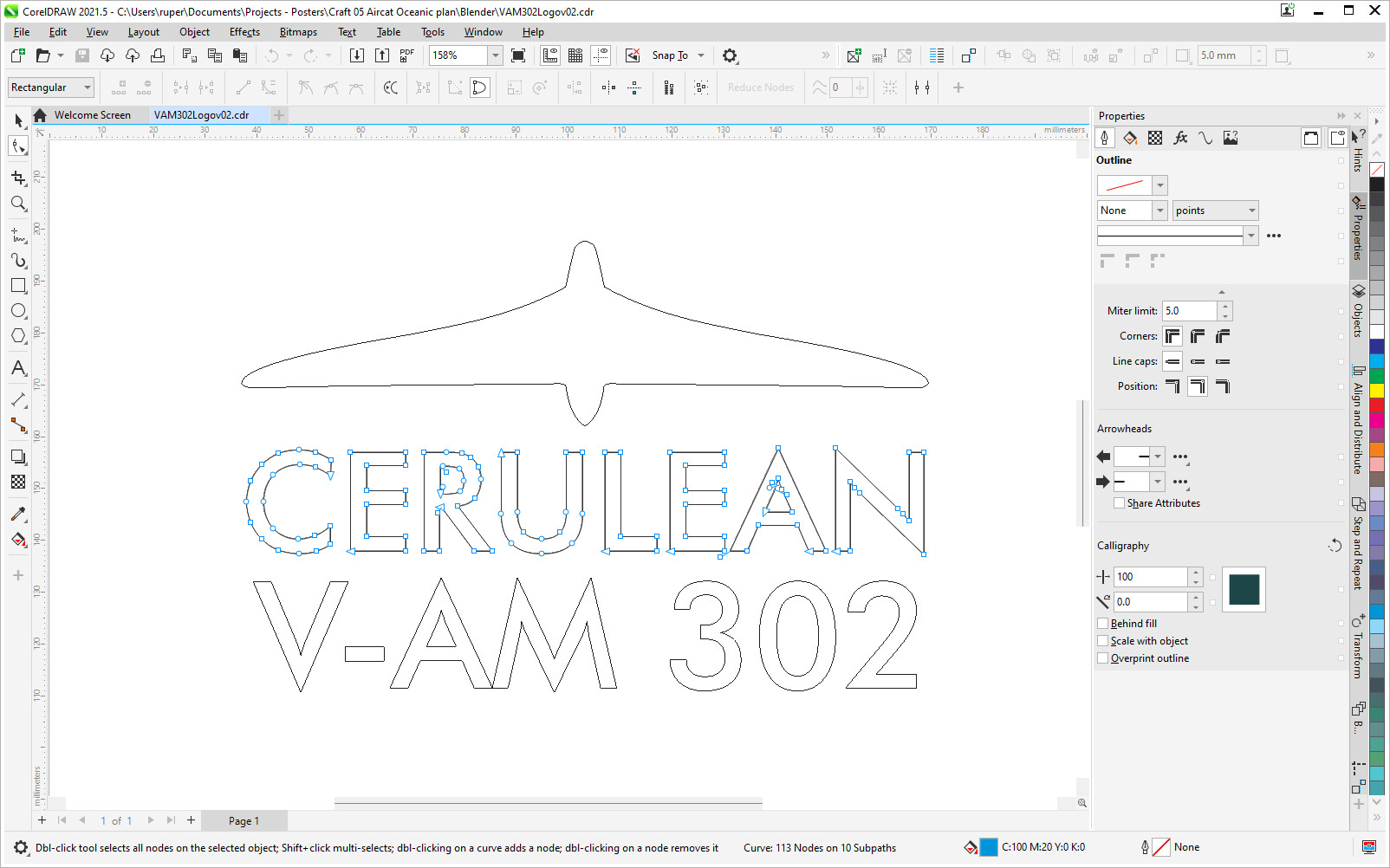
This is a screenshot from CorelDraw, but Inkscape and Illustrator probably work in very similar ways. The Cerulean logo is a curve. It is built from nodes and bezier curves. You cannot assume the same thing about the text. I have found that you have to explicitly turn text into curves using a Convert to curves function (or its equivalent depending on your application). If you don't, the Blender import doesn't work. In the case above you can tell the text is now a curve because the nodes linking the bezier curves are visible. Export your work as an svg 1.1 file. Make sure you have enabled the SVG 1.1 add-on in Blender.
If your file is well formed, once imported - File > Import > Scaleable Vector Graphics (SVG) - the curves will appear somewhere near the world origin and there is a good chance they will be tiny. Almost certainly you will need to zoom in and scale them up a bit to get to a point where they become easy to work with. This is typically what I do next to apply the svg image as a decal:
- Convert the curves to a mesh,
- The mesh will be a weird jumble of vertices, edges and faces in a single plane. I have no idea why they always turn out this way. Check that the faces you want are present and fix up if need be,
- If there are several distinct meshes that need to be manipulated as one, now is a good time to join them together,
- Put the 3D cursor on the part of the plane and then snap the svg mesh to the cursor to get the basic position right,
- Scale, rotate and move the svg mesh to get it to the right size, orientation and position. The mesh is going to be attached to a surface, so to the greatest extent possible align it with that surface,
- Go into Edit mode, select all the faces and extrude them away from the surface just a 'little bit'. This makes the mesh more than just a plane,
- For the svg mesh, apply all transforms and set Origin to geometry,
- Take a backup copy of your svg mesh and move it away - believe me, this is a really good idea because of the next step,
- Now the part which requires a bit of messing about - use a Shrinkwrap modifier to put the svg mesh onto the surface. Look at all the Shrinkwrap options to find the one that works best. Apply the modifier,
- There is a good chance it will look rubbish - for the svg mesh, go into Edit mode, select the top faces of the svg mesh (the ones you previously extruded), and move them away from the surface till you get a decent look i.e. no occlusion.
What could possibly go wrong? A lot - but so long as you have that back-up copy you can keep trying till it looks right, and it will. Apply a material and you're done.
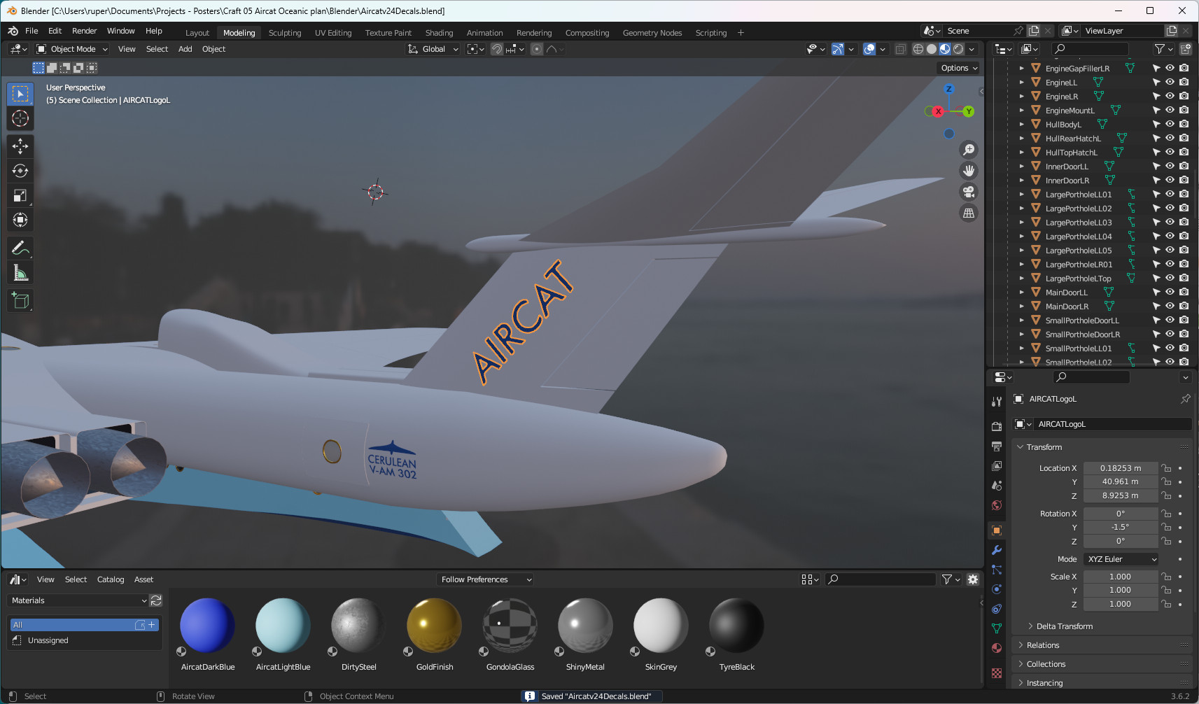
You may find that it seems impossible to get a decent Shrinkwrap. If that is the case, use the Knife tool to add some more geometry to your svg mesh so that it can 'bend' easier to your Shrinkwrap surface. This is the result I got with Aircat.
Materials
10 January 2024
I've said before that I find creating and applying materials as complicated as modelling - but things are getting better. I took a Udemy course to improve my understanding. I haven't finished it yet, but it is helping.
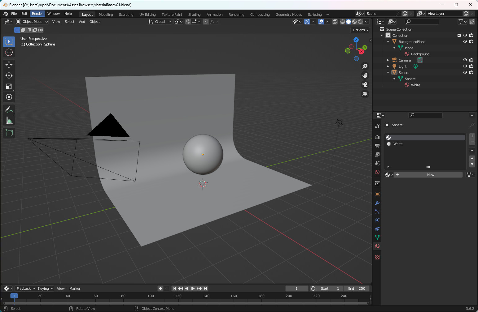
One technique which I'm finding very useful, is the creation of an asset library. My models typically don't need complex materials because of the nature of my poster art. The final posters rely on areas of bold colours that don't have to contain a high level of detail or texture - so the materials themselves can be quite simple. I've started to use a kind of material 'display case' which is just a blend file with:
- A sphere to which you apply your material. A sphere lets you see the effect of the material on curves and at the diameter of the sphere - but you could pick whatever shape you like,
- A background that sits behind the sphere. You give this a colour that lends some contrast to the material you are developing,
- Lights. As many or as few as you like to illuminate your material so you can see how it will behave,
- A camera to get render results.
My display case looks like this:
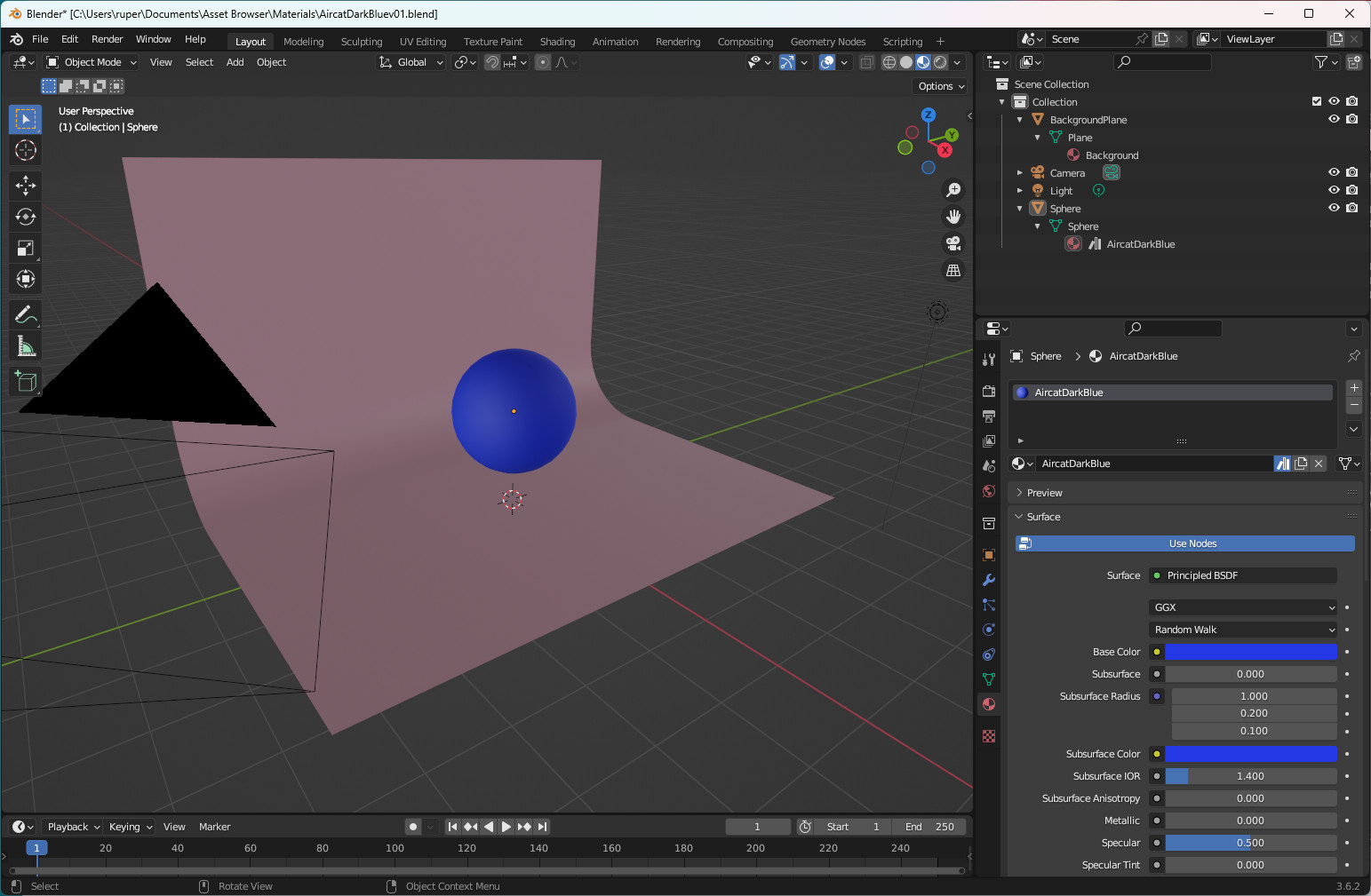
Once you have your display case blend file set up, you can make a copy (always do this) and then work on your material using the material nodes. This is where you can get very sophisticated - or in my case, very simple. Below is the display case for the dark blue colour I used on the bottom of the Aircat hull.
Once you are happy with the material, you can create your asset library:
- Decide where you want to put your assets - and when we talk about assets this can be materials or models. Come up with a directory name like AssetBrowser/Materials, whatever you want,
- In your display case material blender file, in the Outliner window, select the material you have created, right click and select 'Mark as asset'. In the Outline window a little bookcase type icon will appear against your material,
- Save your new display case material blender file into the directory you created to hold your assets, then
- Tell Blender where you are keeping your assets. Go to Edit > Preferences then on the left hand side of the pop-up window find and click on File Paths button. On the right hand side scroll to the bottom and find Asset Libraries and use the + button to add you new asset library name and below that the new path to that directory.
You will probably have to restart Blender for everything to align.
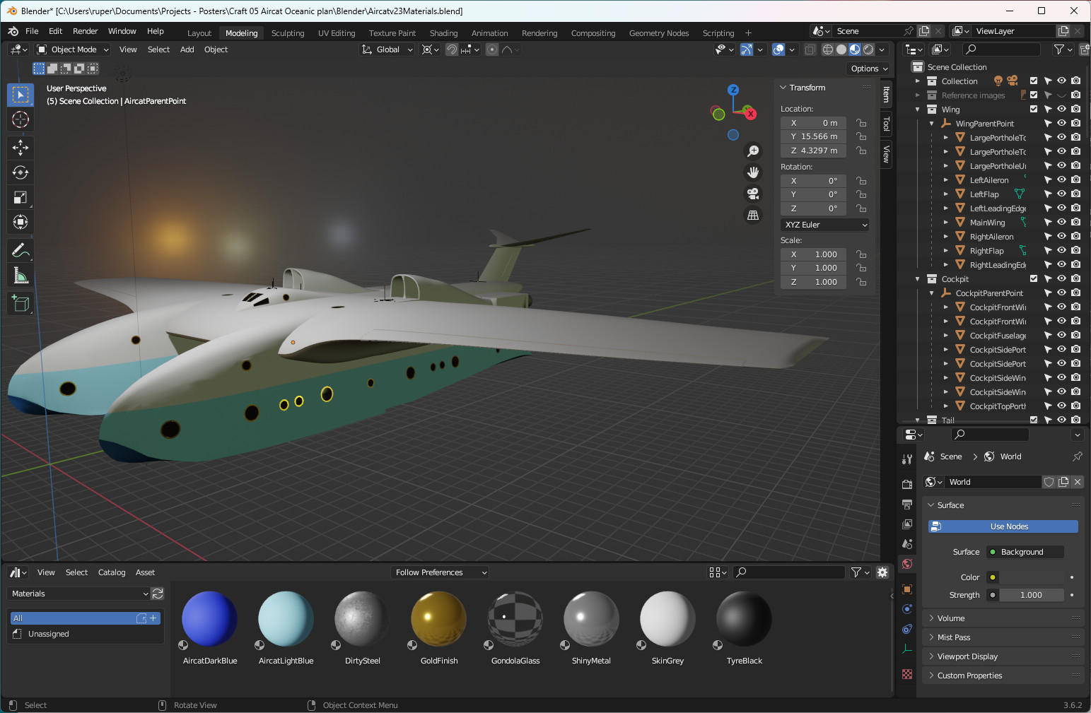
Now, when you want to start applying materials to your model you can open an Asset Browser window below your main window and, when in Object Mode, simply drag material assets from the Asset Browser onto your model to have them applied. If you want to apply a material to part of a mesh in Edit mode, you have to get Blender to understand where the material is. I create a random cube and apply the material to that. Then I find I can pick up the new material in the materials panel and apply it to specific faces in Edit mode. Don't forget to delete the random cube when you're done.
This is Aircat with the Asset Browser window open getting its materials:
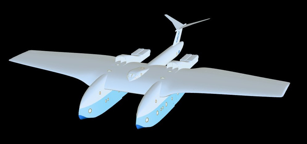
Aircat modelling complete
31 December 2023
I finished Aircat's modelling! Well, you finish and then find you have to tweak something to fix a dodgy piece of mesh, or alter something to help with materials. Whatever, the modelling is finished.
I go through a "cleaning up" process, making use of the Outliner Editor, collections and parents. In the diagram below, in the Outliner on the right hand side, you can see I have created collections for the wing, cockpit, tail and hull. All the pieces of geometry that go to make up those components are properly named and included in the appropriate collection. As I'm modelling, I am always saving bits and pieces - I call these "building blocks" (BB) and I put them into their own collections. I know Blender has some good recovery tools if you make a mistake and need to revert to a previous version. With my BBs I'm just being a bit more proactive.
Within a collection, I add an Empty. This becomes my "parenting point". I parent all the parts of a significant component to the parenting point. That way I can move the component as a whole by moving the parenting point. Then I parent all the parenting points to a single model parenting point which makes moving the model around very easy.
For Aircat I have managed to be a bit more sophisticated with video. Below is a version of the "spinning model".
Aircat cockpit
28 December 2023
The Aircat cockpit sits on the top surface of the wing. The benefit is that the pilots are a long way from the water and spray, but they still need to be able to look down to the water to gauge their distance from the surface for landings and take-offs. To make that possible, the cockpit curves forward down the front of the wing - it has to curve at a higher rate than the wing profile. Going the other way, it gently curves its way to join the wing surface.
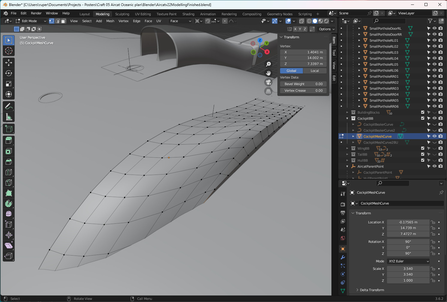
My first attempt was not successful. The strategy was to create a profile - the centre line side profile - and then extrude that sideways, shaping as I went. Two problems emerged:
- The back end was not a smooth gradient down to the wing surface - I ended up creating a ridge as a result of the way I manipulated the geometry.
- I was left with awkward geometry at the edge which I could see was not going to be resolved easily.
You can see those issues in the figure below:
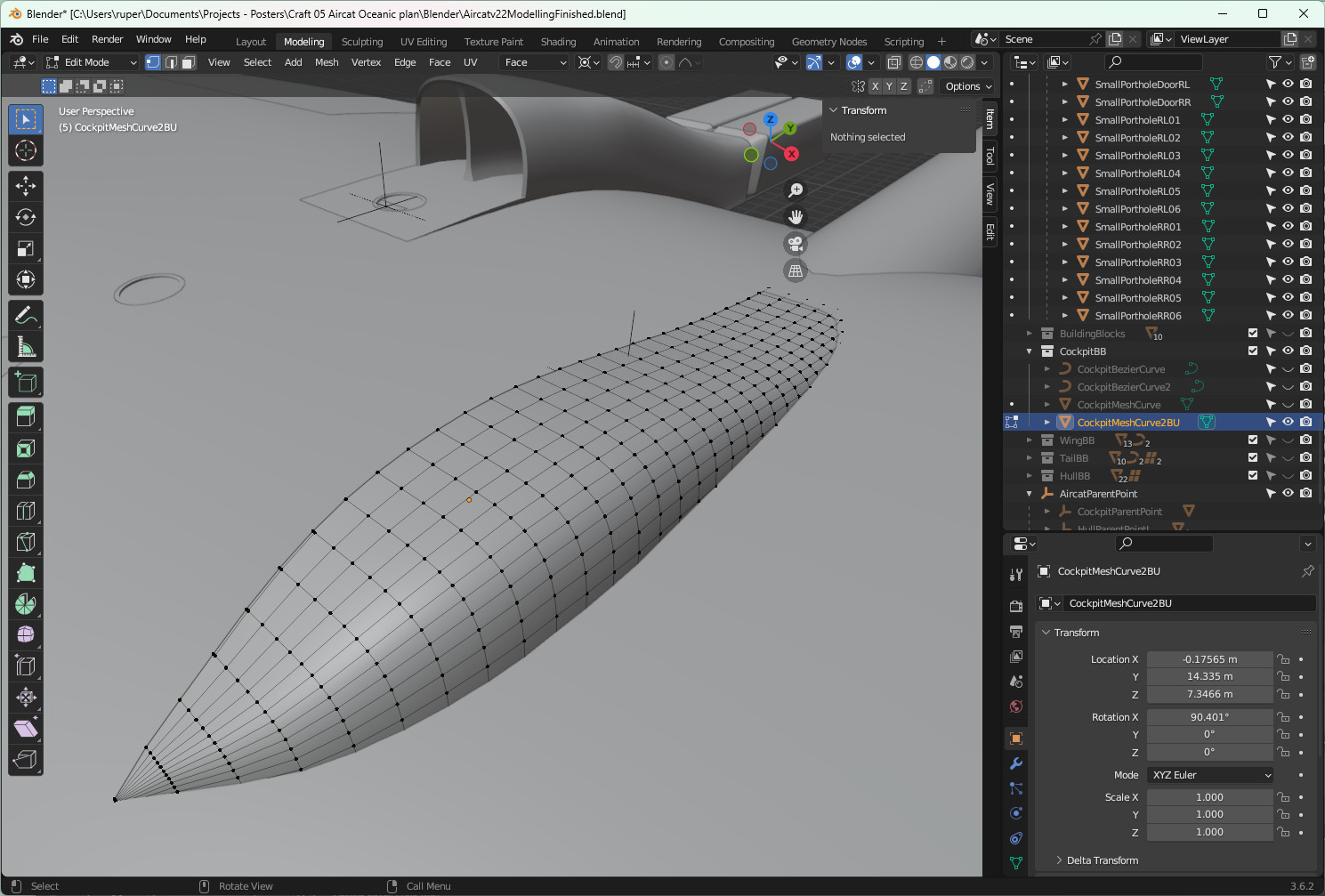
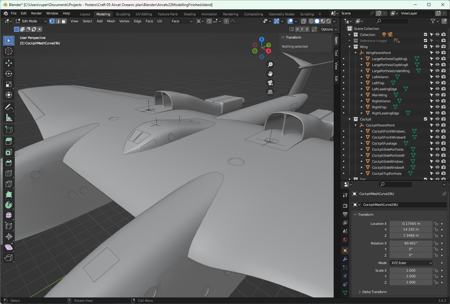
The solution lay in using a cross-section of the cockpit and extruding and shaping forwards and backwards - just as I had done with the hull section. That created a more manageable and malleable piece of geometry.
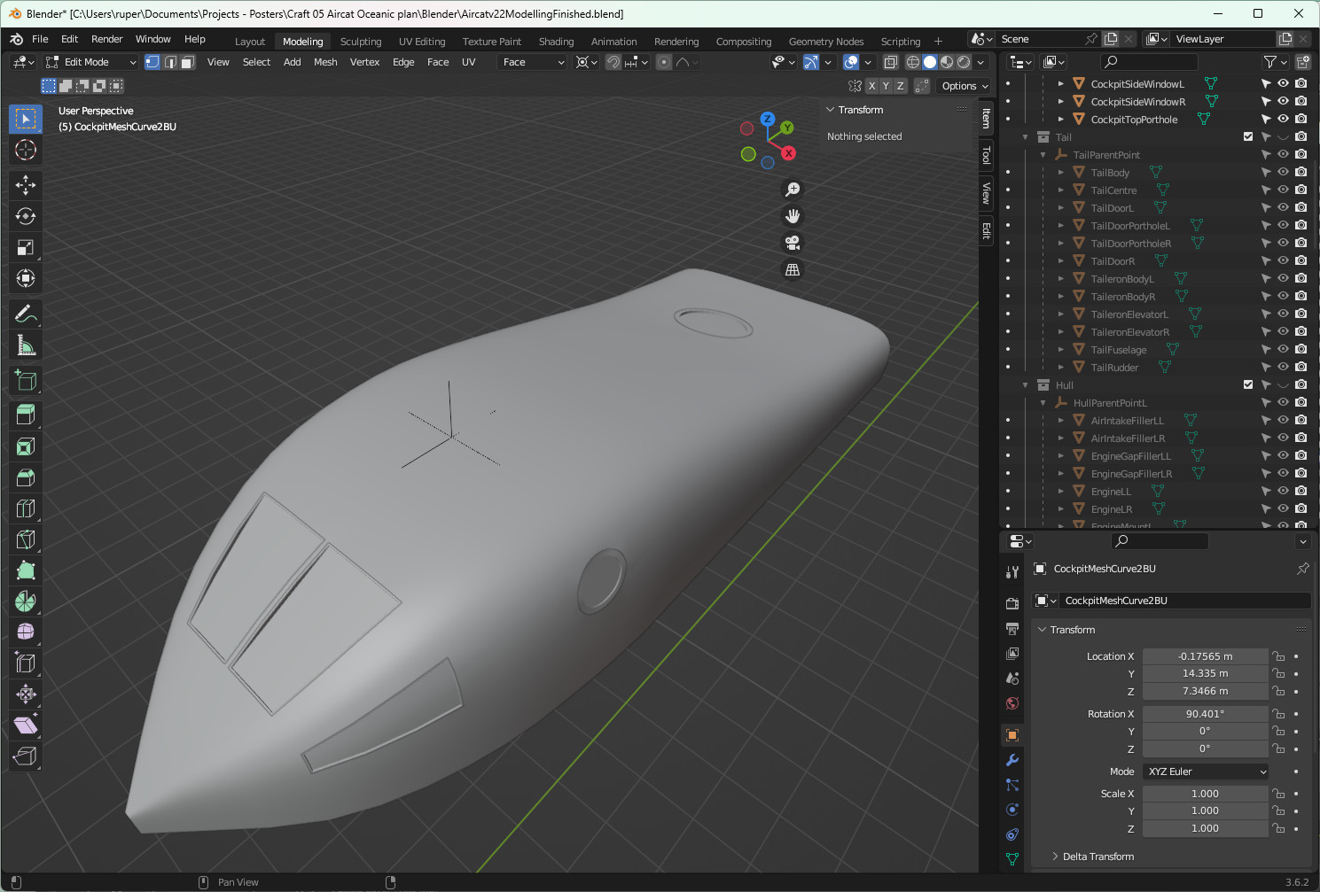
Into this shape I fitted the cockpit windscreen and portholes using my standard window technique, and a mirror modifier. The result:
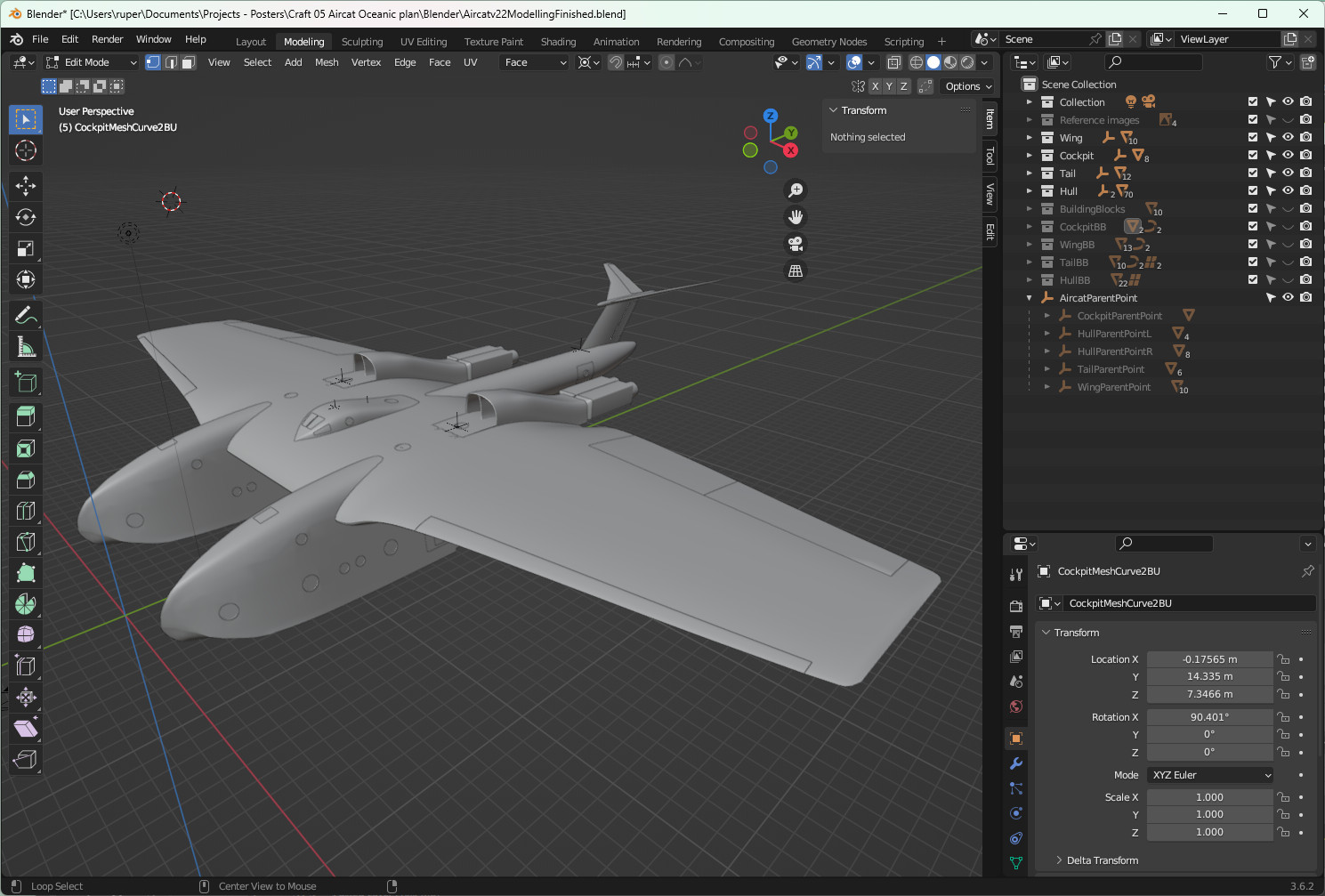
This is the final result. I am quite pleased with that outcome. If I was going to change it, I might give it a less pointy nose - make the tip a bit broader.
Aircat tail
23 December 2023
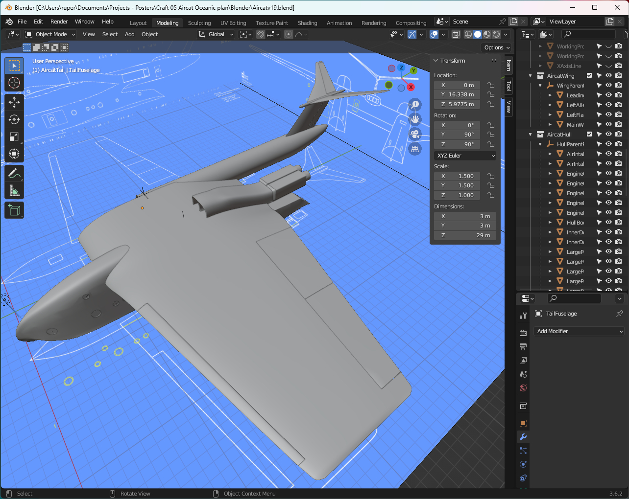
As a flying boat, Aircat needs a high tail to keep it clear of the water and I have unashamebly pinched one of the best looking tails in the business - from the marvelous Handley Page Victor. What an aeroplane that was - in another time it would have been Darth Vader's choice for a private jet.
Like wings, tails are aerofoil shapes and lend themselves to being modelled using bezier curves to get the initial forms correct. That is what I did in this case. I used a lattice modifier to get the right kind of taper across the length of the flying surfaces. I used some of the existing geometry of the tail components and the knife tool to cut out the moving parts of the flying surfaces.
All movable parts have a very small gap between themselves and the fixed parts - obviously to allow them to move. After trying lots of different ways of doing this, the method I prefer is to use the knife tool and slice off very thin strips of mesh from the movable parts. I think that keeps shapes in their truest form - rather than scaling or moving. This is how the tail turned out:
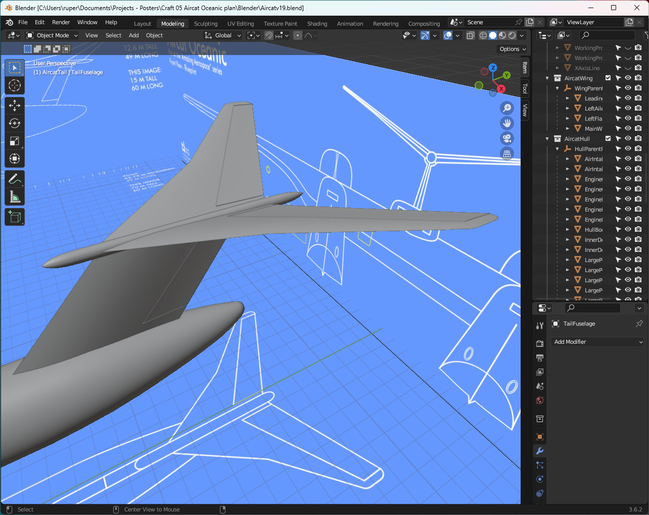
A complete Aircat is getting tantalising close. Together the parts modelled so far look like this:
Aircat windows
16 December 2023
Windows always seem to be problematic. You do your best to create beautifully smooth surfaces and then you have to punch a hole through one to create the window, and some weird geometry in the process.
There are several ways to do it including using the boolean modifier. That does work but I've found that it can be a bit of a blunt instrument and often it is hard to control the outcome - which is where you end up with that weird geometry.
My preferred method at the moment is to take a very planned approach to the creation of the geometry needed to spport the window. On Aircat there are two sizes of window - or porthole. I took the design decision to base the smaller porthole on a circle with 24 vertices. That provided the right balance between getting a good circle shape and not creating too much geometry. The process is:
- Position the porthole circle in the spot where you want the window. Be mindfull of the geometry of the mesh it will be created in. If possible choose a flat face. Orientate the circle to the face - align their normals if possible.
- Using the shrinkwrap modifier, project the circle onto the face. This should ensure that the vertices of the porthole circle are aligned with the face of the mesh. If all looks good, apply the modifier.
- Delete the face of the mesh that the porthole circle was shrinkwrapped to - you'll recreate new faces.
- Use the edge subdivider function to create the same number of vertices around the circle as are contained in the circle.
- Join up those vertices with new faces to create the window hole.
That sounds quite complicated. This picture should make it a lot clearer:
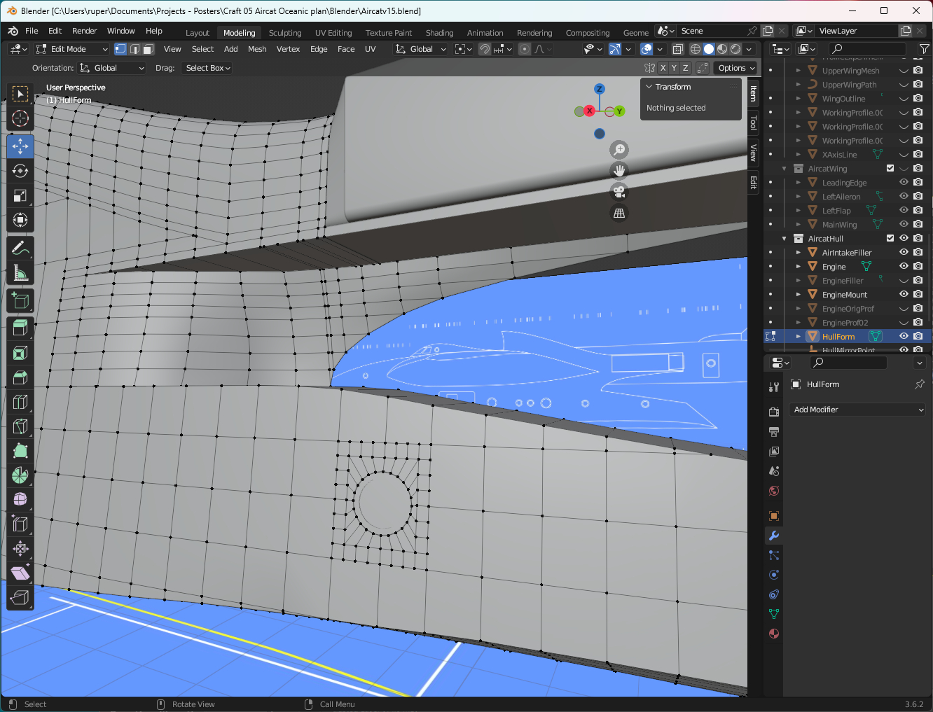
That creates the hole for the window. You then have to decide what the window fitting itself looks like. For Aircat I followed a similar design to that of Tarkine. The figure below shows the Aircat hull with most of its windows and doors installed. The Aircat hull is not symmetrical. The outer facing part of the hull has more windows than the inner facing part. Something to be mindful of before applying any mirrors.
model-viewer in augmented reality mode
9 December 2023
A couple of friends contacted me about Tarkine, model-viewer and that augmented reality mode. It works!
Tarkine is a big model, so when it first appears it looks huge. It is easily scaled down using a "pinch" gesture. This is Tarkine parked on the floor.
This is a short video of Skyluxe having parked itself on the office carpet. Very cool.
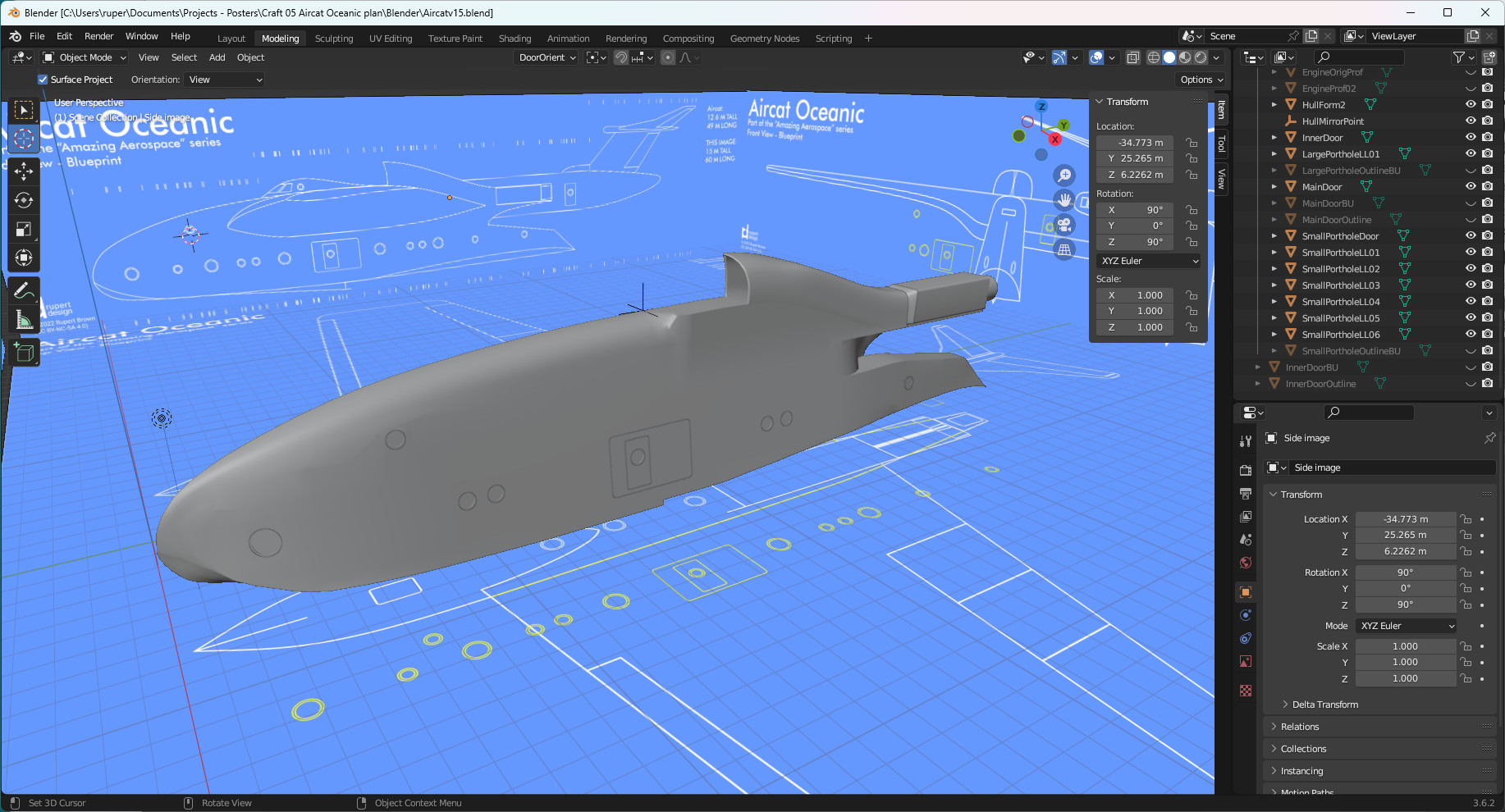
Aircat hull
2 December 2023
The Aircat hull is a very challenging shape - but in a good way. I'm trying to merge the aerodynamics of an aeroplane with the hull of a boat, and add a couple of jet engines. What could possibly go wrong!
I started with the front of the hull. If you look at the references, the large flying boats had tall fuselages to keep wings and engines well away from the water. Aircat follows this design pattern. The hull contains two levels of accommodation requiring several metres of height. As you move towards the front of the hull, the height decreases for the sake of aerodynamics, the width remains the same for the sake of internal accommodation, but the bottom of the hull must be shaped to cut through and remain stable in water. All this comes together at the nose - have a look:
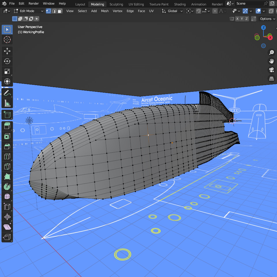
The lower part of the hull not surpringly is the most boat like as this is the part that actually sits in the water. During take off and landings it also has to give the plane directional stability in the water. I included a step in the hull. Steps reduce drag which is important when the plane is accelerating to take off. I threw in a couple of graceful curves thinking about how the water would react with the hull on landing. I formed those curves by extruding then rotating that surface. I think it came out quite well.
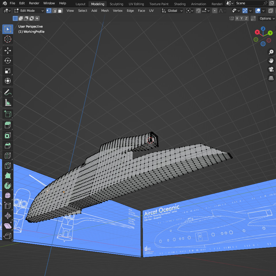
The top part of the hull is the air intakes for the engines and the engine mounts. The intakes sit above the wing to reduce the chance of ingesting too much water. The intakes funnel the air to engines towards the back of the hull - to balance that heavy nose around the centre of the wing - and to sit in line with the centre of mass. The air intakes were relatively straightforward, the only complication being blending them with the slightly wider fuselage.
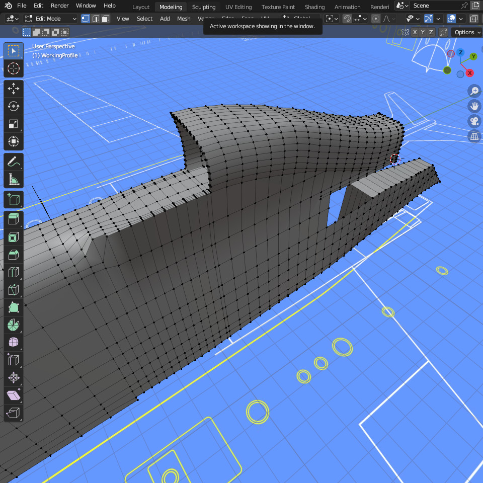
The final piece of the puzzle is also the most complex. I'm still working on how to get it right. It's the section between the lower rear hull and the engine mount. It is supposed to be an engine mount support, and in doing so tapers to a fine edge across its height. Still a work in progress.
model-viewer
25 November 2023
I've seen on other websites those components that let you zoom in and out of and rotate a 3D model. I did a bit of research and found that you can do it using Three.js. That looks like a very capable library but I really wanted something very simple. I found it in a Google project called model-viewer.
This is a straightforward component to set up, but you should be aware of a couple of things - I wasted quite a bit of time on these:
- The model-viewer component has to run in a web server. You can't build a test page on your laptop - it just doesn't work - unless you are running a web server on your laptop which is very possible.
- You have to give the model-viewer component dimensions otherwise it doesn't appear - well, it didn't for me.
- It requires that your model is in glTF/GLB format. My Skyluxe model converted very easily to a .glb file straight from Blender. Tarkine though was very problematic and kept on failing. In the end I converted Tarkine from .blend to .fbx, and then from .fbx to .glb. That seemed to work fine.
The html looks something like this:
In the <head> of your page include the stylesheet and the js, and give it a size ...
<!-- Link to my modelviewer stylesheet. -->
<link rel="stylesheet" href="css/MVStyles.css">
<script type="module" src="https://ajax.googleapis.com/ajax/libs/model-viewer/3.2.0/model-viewer.min.js"></script>
<style>
  model-viewer{
    width:100%;
    height:600px;
    margin: 0 auto;
  }
</style>
In the <body> use the model-viewer component referencing your model ...
<model-viewer src="assets/SkyLuxev06ModelTextured.glb" ar ar-modes="webxr scene-viewer quick-look" camera-controls poster="assets/SkyluxePoster.jpeg" shadow-intensity="1.24" environment-image="assets/aircraft_workshop_01_1k.hdr" shadow-softness="0.85" camera-orbit="26.12deg 80.71deg 477.3m" field-of-view="22.98deg">
   <div class="progress-bar hide" slot="progress-bar">
      <div class="update-bar"></div>
      </div>
      <button slot="ar-button" id="ar-button">
         View in your space
      </button>
      <div id="ar-prompt">
      <img src="assets/ar_hand_prompt.png">
   </div>
</model-viewer>

<!-- modelviewer script -->
<script src="js/MVScript.js"></script>
I created the "look and feel" I wanted in model-viewer's editor and saved the code snippet it produced. The amazing thing you get for free with this Google component is the augmented reality feature. If you open the web page on your phone, you can put the model in your environment (viewed through the phone) and move around it. Quite amazing. These are pictures of Tarkine in model-viewer:
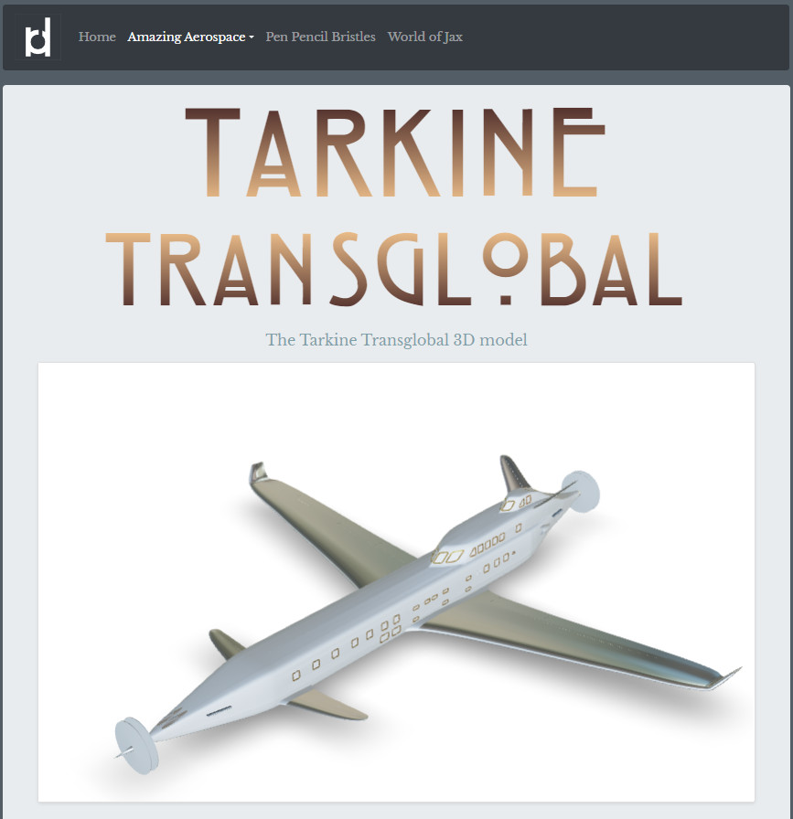
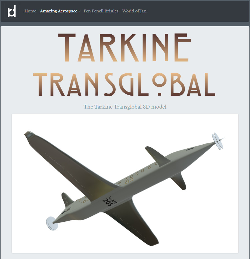
Be patient - it takes a while to load. Skyluxe in model-viewer is here, and Tarkine is here.
Aircat
19 November 2023
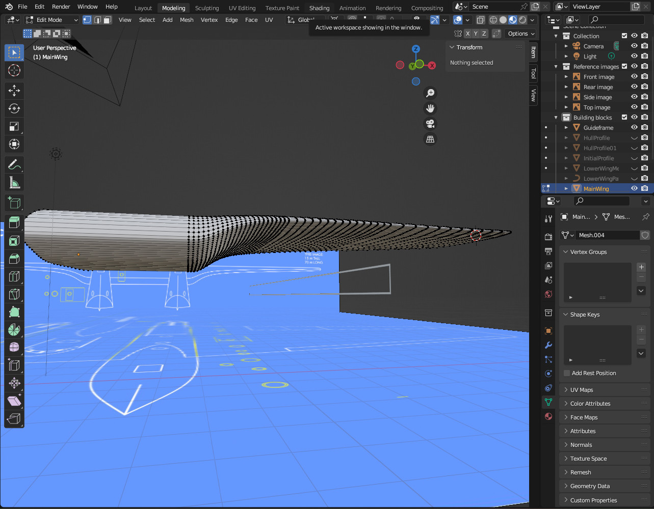
I can tell that modelling Aircat is going to be a challenge - there are lots of strange shapes that morph into other strange shapes. To be kind to myself I started with the main wing as that looks relatively straightforword. I set up Cyber-Rochester, Rochester on Medway in the UK being the home of the great Empire Class flying boats.
The Aircat wing is a special thing and so much more than a conventional wing. It is the structure that holds the whole plane together - the two hulls with the engines, and the tail - so it has to be very strong. Further it is as much fuselage as wing. It contains a significant amount of cabin space. Because of that the middle section is thick - several metres thick. That thickness wouldn't work along the whole wing so it has a significant taper. That gives it its unique shape.
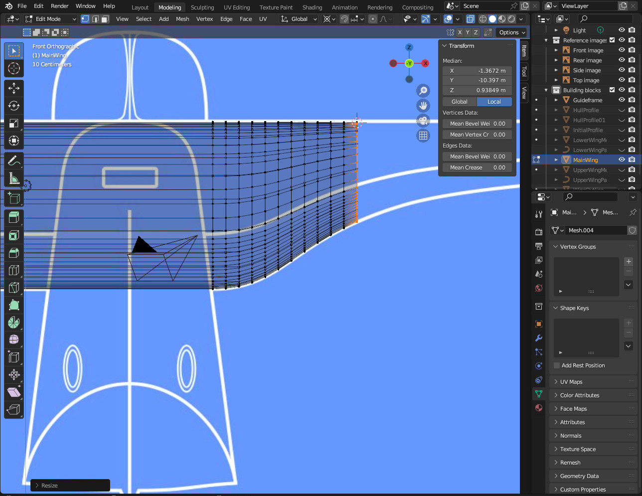
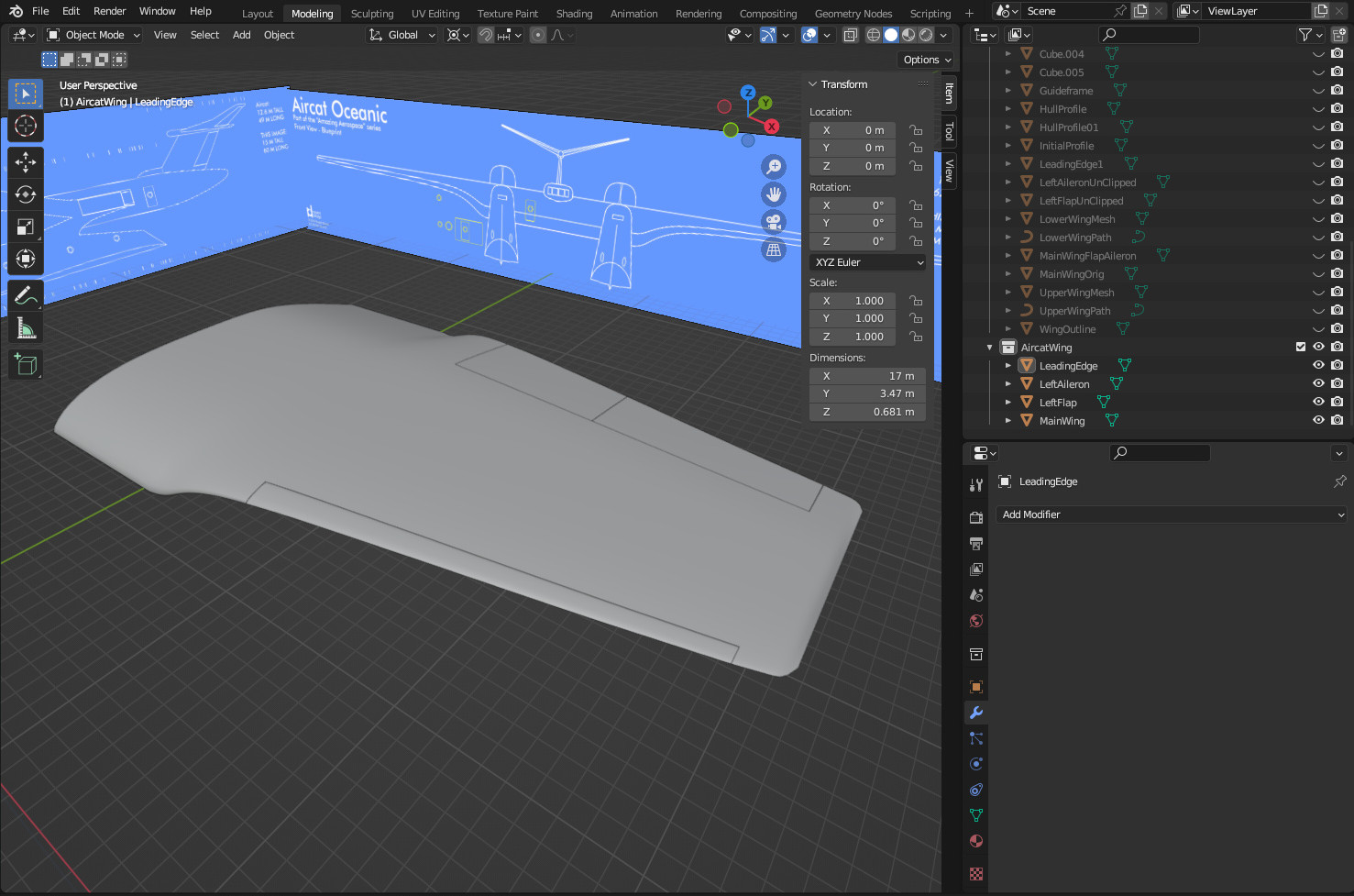
In those parts where the taper is greatest I'm creating a lot of geometry to ensure a smooth finish. As the taper reduces towards the end of the wing I reduce the geometry. I kept the number of vertices on the top half of the wing the same as on the bottom half of the wing. This makes closing off the wing geometry at the tip a bit easier and neater.
The movable flying surfaces are always a good challenge. I select vertices and then duplicate or delete them to create the basic shapes. In the past I've used custom orientations to reduce the size of the flaps and ailerons a little to create small gaps between them and the main wing. This time though I used very precise knife cuts to get to the sizes I wanted. That worked just as well.
Now those hulls are going to be very challenging.
Families
28 September 2023
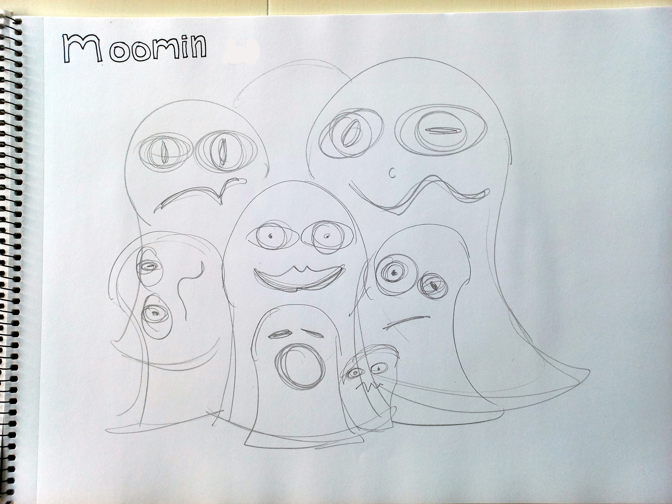
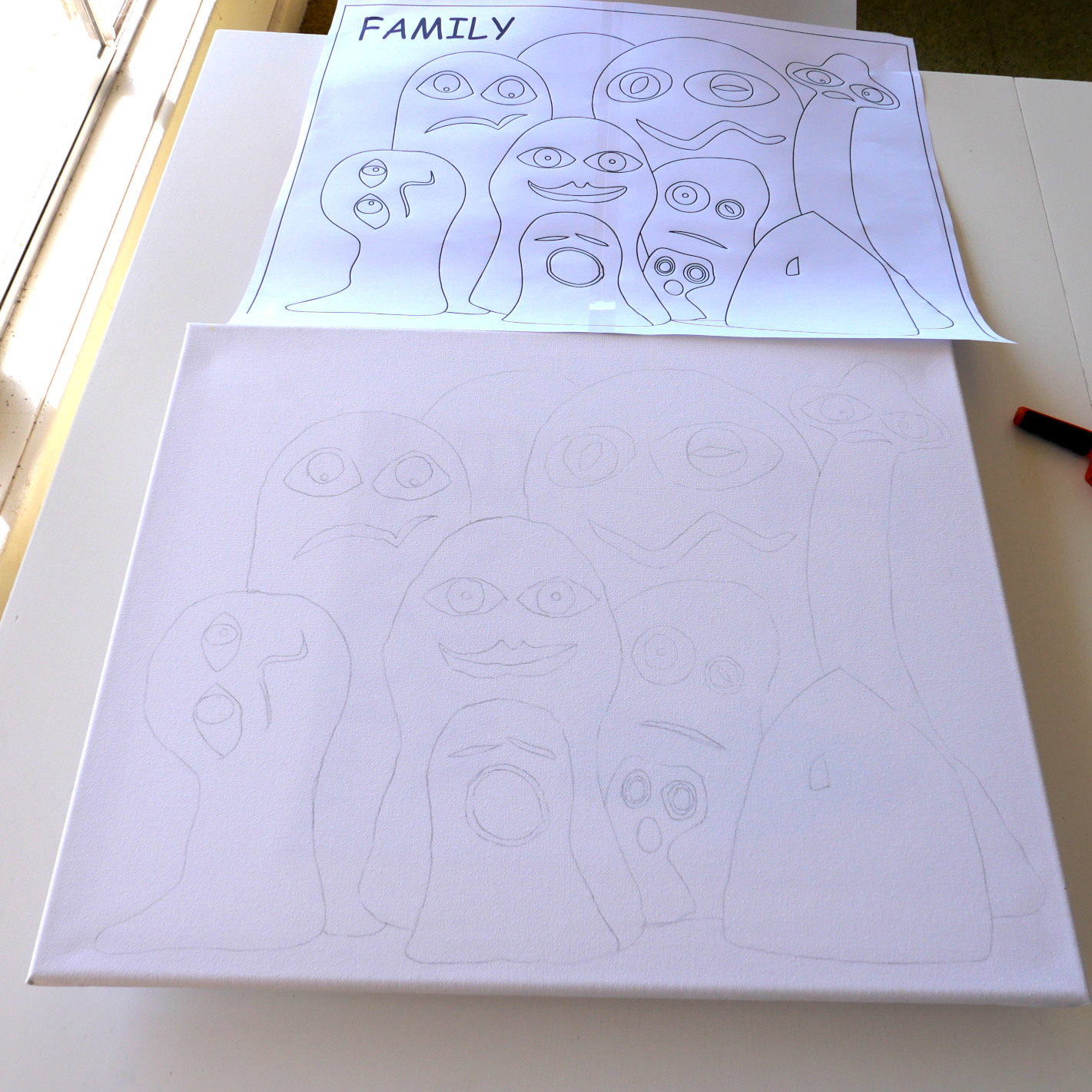
You have just woken up. You are lying in bed with no pressing reason to get up. It is warm and comfortable and you can let your mind wander in that dreamxeam kind of a way where ideas wash over you. I love those moments. For me they seem to be incredibly productive when it comes to new ideas. It was one of those moments that gave me this piece of draftwork - something I'm hoping to turn into a painting. When I did get up, I captured it in a quick pencil sketch. For some reason I called it Moomins. I'm not sure why - I like the word - but they are definitely NOT Moomins. Moomims are the creation of Tove Jansson.
I liked the way that was looking so I fed the image into the computer and used Inkscape to create a cleaner vector based image.
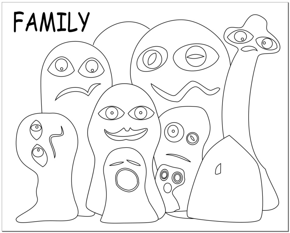
I used Inkscape to size A3 prints to match the size of my canvas. I used the prints to trace (with a 2B pencil) the image onto the canvas. It's ready to go - time to find the paints.
Archive 01
Archive 03
Archive 04
Back to top